The circuit shown generates a signal which is applied to a coil, from which it can be radiated to a test circuit.
The signal creates a low frequency field that can be picked up by transducers and inductive components without connection such as pickup coils, recorder heads, microphones and others, as shown in Figure 1.
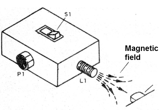
How it works
The circuit consists of a simple audio oscillator with complementary transistors where the frequency is determined by the setting of P1 and the value of the capacitor C1.
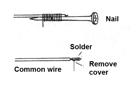
The circuit load is not a loudspeaker, but a coil that can be wound on a nail or a screw with thin wire (28 to 32).
They are wound from 50 to 100 turns of the indicated wire.
The signal generated is rich in harmonics, which can excite both audio and RF circuits.
This allows tests on several circuits to be made, with direct pickup in cases of receivers or other more sensitive circuits.
Circuit power can be supplied with 2 or 4 small batteries.
Assembly
In Figure 2, we give the complete diagram of the injector.
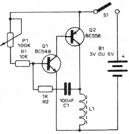
As it is a very simple assembly, even an assembly on a terminal strip, as shown in Figure 3, is possible.
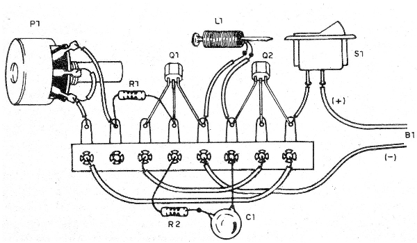
For a more elaborate assembly we have a printed circuit board which is shown in Figure 4.
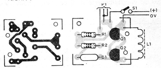
Observe the positions of the transistors in the assembly.
In Figure 5, we have details of the construction of the transducer.
The resistors are 1/8 W and the capacitor can be ceramic or polyester.
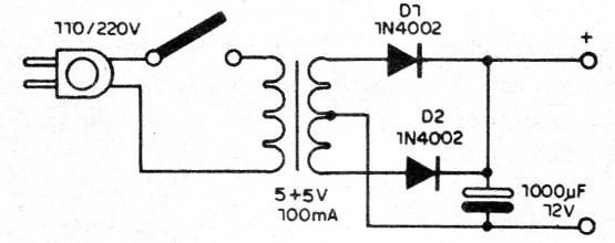
A power supply for the circuit.
To test, simply connect and approach the injection coil of an AM radio tuned out of station.
Q1 - BC548 - NPN general purpose transistor
Q2 - BC558 - general purpose PNP transistor
S1 - Single switch
B1 - 3 or 6 V - 2 or 4 small battery cells
P1 - 100k ohms - potentiometer
X1 - injection coil - see text
R1 - 10 k ohms - resistor - brown, black, orange
R2 - 1 k ohms - resistor - brown, black, red
C1 - 100 nF - polyester or ceramic
Miscellaneous:
Printed circuit board or terminal bridge, battery holder, mounting box, wires, welding, etc.


