Note: this article is part of my book Science Fair and Technology Education Projects published in USA
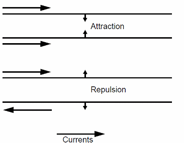
The force acting on the wires can be used in a scale that measures the amount of current through a circuit. This scale is named ‘Ampere Scale’ due to his creator, Jean Marie Ampère, a French scientist who also gives his name to the current unit. The Ampere Scale described here is not like the original, but a very simple version, using common and cheap parts.

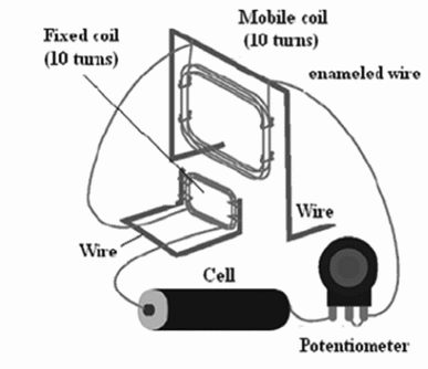
Figure 2 shows details of the construction of the scale. The parts can be installed on a wood base or some other material.

The coils, consisting in about 10 turns of enameled wire each one, are placed as indicated in the figure. The point where the wires are connected must be uncovered to guarantee a good electric contact. In order to maintain a perfect electric contact, it is recommended a soldering connection or the use of screw terminal strips.
Explaining the Experiment
When the circuit is closed (the cell is placed in the circuit), a current flows across the coils creating magnetic fields. The magnetic field force lines direction of the magnetic field determines the direction of the forces acting on the coils (repulsion or attraction).
The forces will move the coils by an angle that depends on their intensity. By observing the angle, you can measure the intensity of the current flowing through the circuit. The potentiometer used in this experiment allows the reader to change the current and observe the variations in the angle of the coils.
A graduated scale can be added to the circuit having as reference the currents determined by the resistance of the potentiometer.
The Experiment
First, adjust the potentiometer to its lowest resistance, closing it all the way to the left. Touch the input wires to the cell closing the circuit. The moving coil should move by a certain angle (if the coil move in the opposite direction, change the connection of one of the coils).
Repeat the experiment increasing the potentiometer’s resistance until the maximum. Observe that the angles of the moving coil will be reduced by the same grade. Don’t keep the cell connected to the circuit for long time intervals. The current drain of the circuit is high, running down the cell quickly.
Suggestions
A) Connect a Multimeter in the current scale in series with the circuit to measure the current flowing through it.
B) Draw a graphic where you plot the current versus the angle. Study the linearity of the scale.
20 to 30 meters of enameled wire—gauge 22 to 28 AWG
1 wood base
2 meters or rigid wire—gauge 16 to 18 AWG
1 piece of cotton thread
1 C or D cell or 2 cells and a cell holder
1 100 ohm potentiometer
FIM LITA
Competition
Choose among the projects of your pupils who built the more sensitive scale. The most precise scale can also receive a prize.
Questions
1. Explain the operation of the Ampere Scale.
2. Draw the magnetic fields of the wires and explain why repulsion and attractions occurs.
3. Give examples of applications where the principle studied here is applied.


