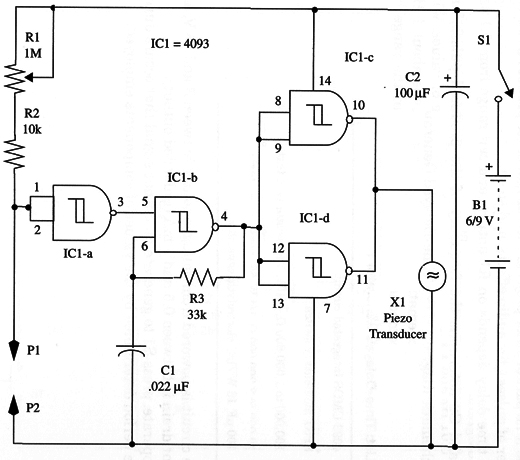
You can probe small components with this simple circuit. Components such as diodes, lamps, fuses, coils, switches, and many others can be tested with this tester, which produces a continuous tone with low-resistance devices.
The circuit can be powered from 6 or 9 V supplies, and current drain is very low. With the tone off, current drain is only 0.5 mA, and when the tone is on, current drain is about 5 mA. R1 adjusts sensitivity.
A schematic diagram of the Fixed-Tone Continuity Tester is shown in Fig. 1.

All of the components can be housed into a small plastic box. R1 adjusts sensitivity.
The circuit can be powered from AA cells or a battery. X1 is a piezoelectric transducer or crystal earpiece.
IC1 - 4093 CMOS integrated circuit
X1 - Piezoelectric transducer or crystal earpiece
S1 - SPST toggle or slide switch
B1 - 6 or 9 V, four AA cells or battery
P1, P2 - Black and red probes
R1 - 1,000,000 ohm - potentiometer
R2 - 10,000 ohm, 1/4 W, 5% - resistor
R3 - 39,000 ohm, 1/4 W, 5% - resistor
C1 -l 0.022 µF - ceramic or metal film capacitor
C2 - 100 µF, 12 WVDC - electrolytic capacitor


