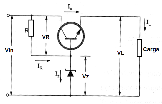
The configuration shown in figure bellor is the basic voltage regulator using a zener diode as reference and a transistor to control the load current. The following formulas are used when calculating the elements in this circuit:

Starting Point:
In a practical project it is important to start from some fixed parameters and calculate the used components from them. The fixed parameters to be used in the next formulas are:
Fixed:
VL = voltage in the output (load) in volts (V)
Vin(min) = minimum input voltage in volts (V)
Vin(max) = maximum input voltage in volts (V)
Vin = input voltage (value between Vin(max) and Vin(min) - normally the variation of the input voltage adopted in the projects are 10%) in volts (V)
Iz(min) = minimum current through the zener (indicated by the manufacturer) in amperes (A)
IB(max) = maximum value of the base current (indicated by the manufacturer or chosen according the transistor gain as function of the load current) in amperes (A)
Important: Vin>Vz
Formula 1
Load voltage:
VL = VZ + VBE
Where:
VL is the load voltage in volts (V)
Vz is the zener voltage in volts (V)
VBE is the voltage fall in the base-emitter junction (typically 0.6 V to silicon transistors).in volts (V)
Formula 2
Voltage accross R:
VR = Vin - Vz
Where:
VR is the voltage accross R in volts (V)
Vin is the input voltage in volts (V)
Vz is the zener voltage in volts (V)
Note: the input voltage must be greater than the zener voltage to correct operation. A difference at least of 3 volts is recommended in normal projects.
Formula 3
Iz(max):
Iz(max) = { [ Vin(mx) – Vz ] / [ Vin(min) – Vz ] } x [ Iz(min) – IB(max) ]
Where:
Iz(max) is maximum current in the zener diode in amperes (A)
Vin(max) is the maximum input voltage in volts (V)
Vin(min) is the minimum input voltage in volts (V)
Vz is the zener voltage in volts (V)
Iz(min) is the minimum current the zener in amperes (A)
IB(max) is the maximum current in the transistor's base in volts (V)
Formula 4
IB(max)
Iz(max) = Ic(max) / B(min)
Where:
Iz(max) is the maximum current in the zener diode in amperes (A)
Ic(max) is the maximum current in the transistor collector (load current) in amperes (A)
B(min) is the minimum gain of the used transistor
Formula 5
Zener dissipation:
Pz = Iz(max) x Vz
Where:
Pz is the minimum power dissipation of the used zener in watts (W)
Iz(max) is the maximum current in the zener diode in amperes (A)
Vz is the zener voltage in volts (V)
Formula 6
Calculating R:
Rmin = [Vin(max) – Vz ] / Iz(max)
and
Rmax = [ Vin(min) – Vz ] / [ IB(max) + Iz(min) ]
Rmin < R < Rmax
Where:
R is the chosen resistor in ohm (Ω)
Rmin is the minimum value for R in ohm (Ω)
Rmax is the maximum value for R in ohm (Ω)
Uin(max) is the maximum input voltage in volts (V)
Uin(min) is the minimum input voltage in volts (V)
Uz is the zener voltage in volts (V)
Iz(max) is the maximum current in the zener diode in amperes (A)
Iz (min) is the minimum current in the zener diode in amperes (A)
IB(max) is the maximum base current in the transistor in amperes (A)
Formula 7
Power Dissipation of R:
P = VR2 / R
Where:
P is the power dissipated by R in watts (W)
UR is the voltage accross R in volts (V)
R is the resistance in ohms (Ω)
Formula 8
Minimum input voltage:
Vin(min) = Vz + R[ Iz(min) + Ib(max) ]
Where:
Vin(min) is the minimum input voltage in volts (V)
Vz is the zener voltage in volts (V)
R is the resistance in ohm (Ω)
Iz(min) is the minimum current in the zener in amperes (A)
Ib(max) is the maximum current in the transistor base in amperes (A)
Formula 9
Determining minimum B for the transistor:
B(min) = Ic(max) / Ib(max)
Where:
B(min) is the minimum gain of the used transistor
Ic(max) is the maximum current in the transistor (load current) in amperes (A)
IB(max) is the maximum base current in the transistor in amperes (A)
Application example:
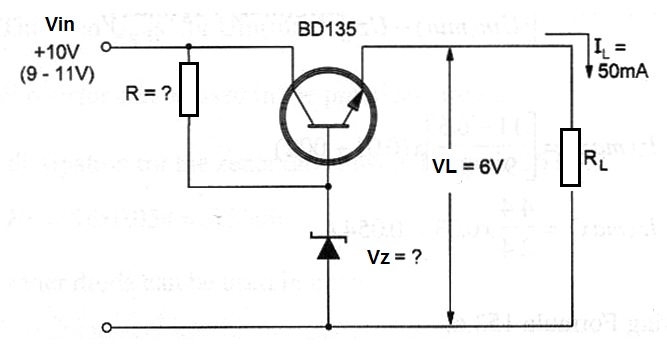
Calculate the practical elements to a voltage regulator with the configuration shown in figure 2 starting from the next data:

Data:
Vin = 10 V (10% of variation)
Vin(max) = 11 V
Vin(min) = 9 V
VL= 6 V
IL = 500 mA
Zener parameters will be fixed after the voltage is determined.
a) Calculating Uz using formula 1:
Vz = Vin + 0.6 (we intend to use a silicon transistor)
Vz = 10 - 3.4
Vz = 6.6 V
(we adopted the voltage average input value)
b) Calculating VR
VR = Vin – Vz
VR = 10 – 6.6
VR = 3.4 V
c) Determining Iz(max) using formula 4:
Iz(max) = { [ Vin(max) – Vz ] / [ Vin(min) – Vz ] } x [ Iz(min) + Ib(max) ]
Iz(max) = [ ( 11 – 6.6 ) / ( 9 – 6.6 ) ] x ( 0.01 + 0.02 )
Iz(max) = ( 4.4 / 2.4 ) x 0.03
Iz(max) = 0.054 A
d) Calculating R: (formula 6)
Rmin = (11 – 6.6) / 0.054
Rmin = 4.4 / 0.054
Rmin = 81.4 Ω
Rmax = ( 9 – 6.6 ) / ( 0.02 + 0.01 )
Rmax = 3.4 / 0.03
Rmax = 113 Ω
81.4<R
Use a 100 Ω resistor for R.
e) Determining the minimum B for the transistor (formula 9)
B(min) = 0.5/0.02 = 25
f) Determining the power dissipation of R: (formula 7)
Pr = 3.42/100 = 0.11 W
The used UR is for Vin(max).
A 1/4 or 1/2 W resistor can be used in the practical circuit.
g) Calculating the dissipation for the zener diode: using formula 5:
Pz = 6.6 x 0.054 = 0.356 W
A 1/2 or 1 W zener diode can be used in practice.


