Biological processes are usually accompanied by electrical manifestations which can be detected by sensitive external circuits. For example, neurons generate electrical impulses which can be detected by external circuits, as well as the heart and brain that can have their signals analyzed by electrocardiographs and electroencephalographs. Plants also generate electrical signals which can be detected by a polygraph.
The signals of these processes have amplitudes of a few millivolts requiring circuits of high sensitivity and input resistance. The circuit we describe serves a number of important biological applications.
a) Lie detector
If, under interrogation, a person under stress hesitates to answer an embarrassing question, minor changes in his/her nervous state occur with consequent electrical manifestation.
Polygraphs monitor the currents generated by the person, detecting small variations, which are usually shown in a graph, as shown in Figure 1.
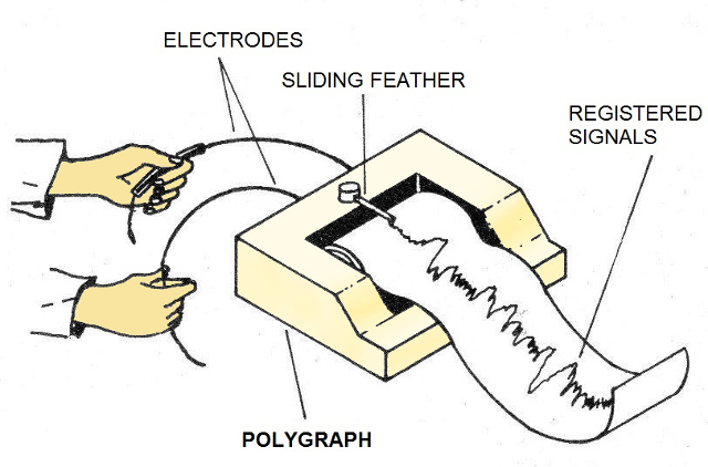
An abnormal oscillation of the chart may mean a lie.
b) Life detection
Searching for lives on other planets has long been important, such as those conducted recently by the Oportunity probe on planet Mars.
What is currently being done is to use the electrical signals eventually generated by the microorganism to detect their presence. Thus, as shown in Figure 2, if we have a sample of nutrient substance exposed and some microorganism falls into it, having a rapid reproduction, the generated signals can be picked up and transmitted to earth.

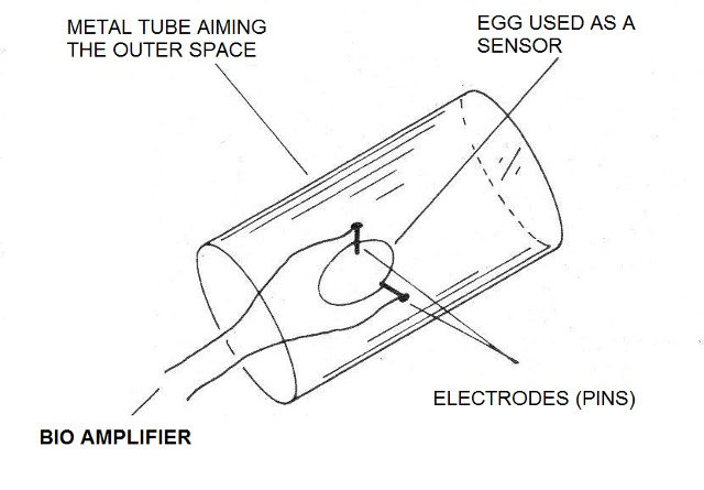
Another life detector is shown in Figure 3, where physiological changes of an egg in an appropriate chamber allow the presence of microorganisms to be detected.
c) Bio Feedback
Interesting behavioral experiments can be done based on the changes in the resistance of our skin which occur under various states of our consciousness. These experiments allow you to control external devices or they can simply be monitored with a device such as the amplifier we describe.
d) Biology Experiments
In the biology lab a number of interesting experiments can also be performed.
In Figure 4, we show how to capture stresses generated on the leaf of a plant to detect biological activity.
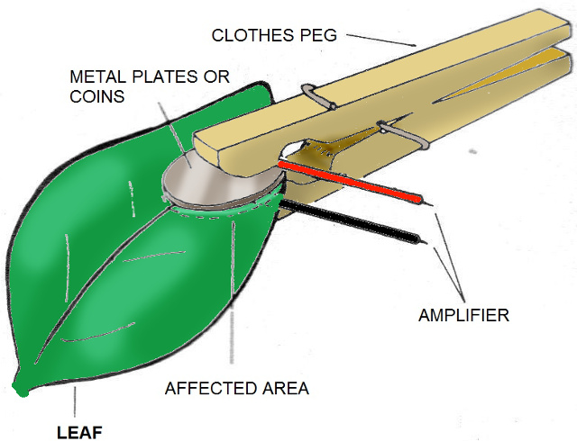
The Backster Effect (Cleve Backster - The Secret Life of Plants) is named after its discoverer who found reactions to external stimuli in plants, indicating that they have a rudimentary nervous system.
Plants can thus perceive the presence of people and even those that tend to cause them harm.
How it works
At the input of our circuit, we have a very high input resistance operational amplifier whose gain can be controlled by a feedback potentiometer. In the input circuit, we also have a low voltage polarized source that is required in experiments where a galvanic effect can generate a small continuous voltage that overlaps the signal.
This current is also unwanted because it causes the electrodes used by electrolysis to deteriorate. The operational amplifier signal is applied to a range of 17 moving bar-type LEDs with LM1914 integrated circuits.
Thus, the number of LEDs which light up on the digital scale will depend on the input signal voltage. The scale will also have a dynamic response if the signal varies over time, which is very interesting in experiments involving reaction periods.
Assembly
We start by giving the complete circuit of the biological amplifier or bioamplifier in Figure 5.

For the assembly, we suggest the printed circuit board shown in Figure 6.
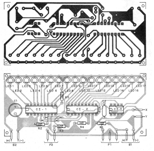
When assembling, observe the position of the integrated circuits and the polarity of the LEDs, as inversions will prevent the circuit from functioning.
The signal input cable must be shielded so that noise pickup does not affect the operation. The circuit has a very high input resistance and is therefore extremely sensitive to snoring.
Power should be from medium to large batteries, given the consumption when all LEDs are lit. If using a power supply, it must have excellent filtering and be isolated from the network by using a transformer.
Do not use a transformerless power supply to power this circuit.
Test and Use
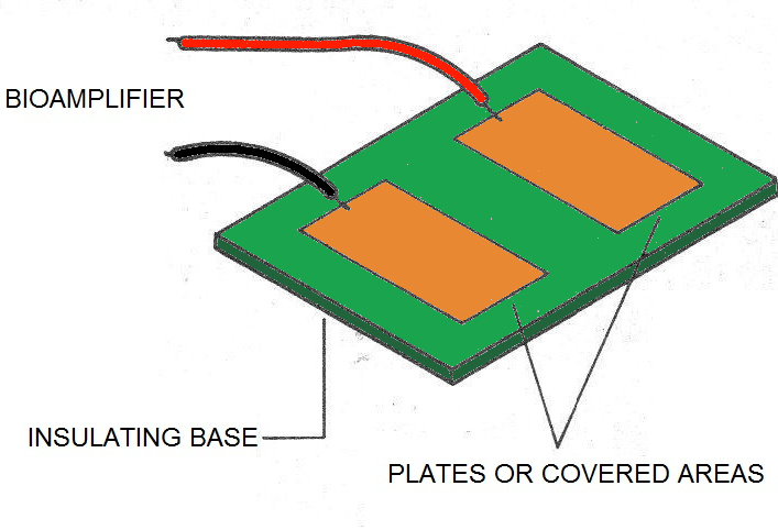
Turn on the power and input a sensor to place your fingers, as shown in Figure 7.
By adjusting the controls and pressing your fingers on the sensor, the LEDs should light up by varying the amount. Keep in mind the limits of the device by not applying intense signals to its input.
CI-1, CI-2 - LM3914 - Integrated Circuits
CI-3 - CA3140 - Operational Amplifier
LED1 to LED17 - Common LEDS
B1 - 6 to 12 V - batteries
B2 - 1.5V - small battery
P1 - 100 k ohms - Potentiometer
P2 - 2M2 - Potentiometer
C1 - 100 uF x 12 V - electrolytic capacitor
C2 - 47 nF - Ceramic or Polyester Capacitor
S1 - Dual Switch (Conjugated)
R1 - 47k ohm x 1/8 W - resistor - yellow, violet, orange
R2 and R4 - 10k ohm x 1/8 W - resistors - brown, black, orange
R3 - 1k5 ohm x 1/8 W - resistor - brown, green, red
R5 - 22k ohm x 1/8 W - resistor - red, red, orange
Miscellaneous:
Printed circuit board, battery holder, assembly box, wires, welding, etc.

