The resonant frequency of a parallel LC circuit, as shown in Figure 1, and used for tuning different receivers and transmitters is given by Formula (1).
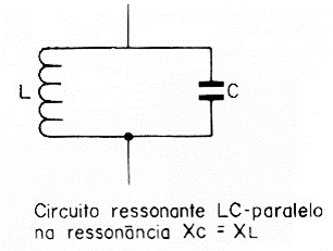

Where:
f is the frequency in hertz (Hz)
2 x PI is the constant 3.14 multiplied by 2 resulting in 6.28
L is the coil inductance in henry (H)
C is the capacitance in parallel given in farads (F)
Remember that 1 µH equals 10-6H and that 1 pF (PF) equals 10-12F.
This formula, which is quite simple, does not work to directly solve the main problems, as it allows calculating only the resonance frequency of a circuit when the inductance and capacitance are known.
In practice, what is easier is to know the maximum and minimum capacitance of the associated capacitor, generally variable (or trimer), which allows us, in principle, to set the limits of the range which will be covered by the circuit.
For inductance, we have no more information than possible dimensioning.
Thus, we need to not only adapt our basic formula for solving problems, but also use our own, which relates the coil inductance to its dimensions. See Figure 2.
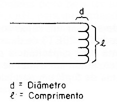
The coefficient of self-induction, or simply the inductance of a coil or solenoid with an air core, is given by Formula (2).
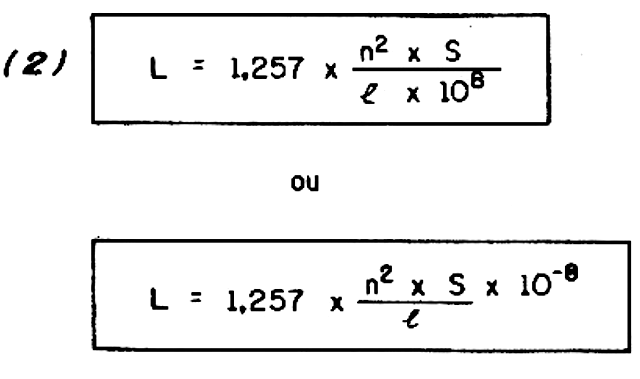
Where:
L is the inductance in henry (H)
n is the number of turns of the coil
S is the section covered by a loop in square centimeters
I is the length of the solenoid in centimeters.
Note that, to calculate the section covered by a loop from the diameter, we use Formula 3.
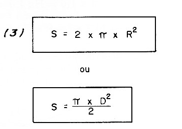
Where:
PI is 3.14, being constant
D is the diameter of the coil.
The adequacy of Formula (2) and that of Formula (1) results in the following improvement for solving our problems.
The first formula is the Formula (4):
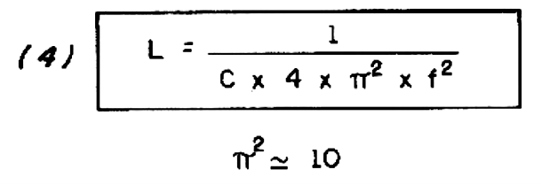
Where:
The symbols are the same as the others, with the same meanings, therefore. With it we can determine what the inductance of a coil should be to tune, with a given capacitance and a certain frequency. We can apply this formula to an all closed, variable and have the lower end of the range and then to the all open variable to have the upper end.
Note that in the formula, the frequency is inversely proportional to the square of the inductance. This means that if the inductance varies from a certain X, keeping the capacitance fixed, the frequency will change in the square root of X.
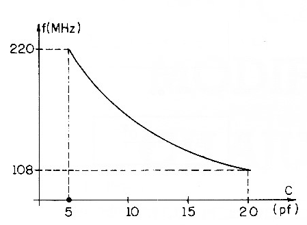
In Figure 3, we give a simplified graph that shows the variation of the frequency with the capacitance, in percentage terms.
The second derivative is the Formula (5):

Where:
The symbols also have the same meanings in it.
With Formula (5), it is determined how many turns in a fixed diameter the coil must have to tune to a certain frequency, this with the variable in a position of known capacitance (min. or max.).
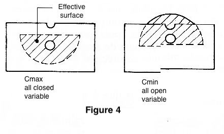
Thus, we can apply the formula for Cmin (all open variable) and determine the upper end of the tuned range. Then applying for Cmax (all closed variable), we can calculate the lower end of the tuned range. See Figure 4.
The procedures indicated are interesting, especially for projects involving FM and VHF transmitters and receivers.
Examples of practical application
Let us take as an example of application of these formulas the determination of the characteristics of a resonant circuit to be used in a receiver which must tune the VHF band from 108 MHz.
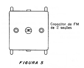
It is intended to use a variable capacitor Toko mod 2Q - 20ET3 with two sections which has a maximum capacitance of 20 pF and also has a maximum capacitance trimmer of 5 pF in parallel. See Figure 5.
We start by calculating the coil inductance.
Where:
f = 108 MHz = 108 x 106 Hz
C = 20 pF = 20 x 10-12 F
L = must be calculated
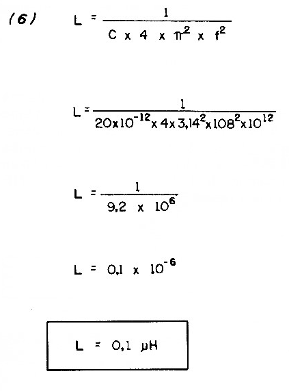
The coil must therefore have an inductance of 0.1µH, so that when the variable is all closed (ignoring the action of the trimmer), a frequency of 108 MHz is tuned. With the variable all open, the frequency should be higher, as we will calculate at the end of our considerations.
How many turns should this coil have
For the VHF range, it is common to use self-supporting coils (without core) with a diameter of the order of 1 cm, and equal length. See Figure 6.

Experience shows that, with few turns, we reach the desired inductance. We then apply the Formula (7), fixing the values ??of the inductance, length and section covered by a loop.

Where:
L = 0.1 µH = 0.1 x 10- 6 H
I = 1 cm
S = 2 x PI x R = 2 x 3.14 x 0.5 = 3.14cm
Note that for a diameter of 1 cm we have a radius of 0.5 cm, a value used in this formula.
The developed expression leads us to the result (8)
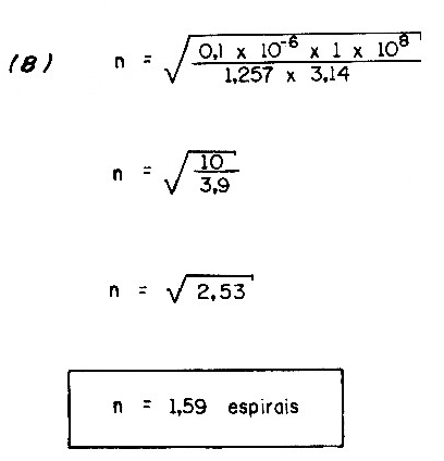
We must, therefore, roll a loop and a half to obtain the coil in question, with good approximation. See that compensations can be made after two ways:
a) The performance of the trimer.
b) By the contraction of the turns. By tightening the coil, we increase the inductance and thereby reduce the frequency.
Now, let’s calculate the upper limit of the tuned band:
For this, we will assume that the minimum capacitance of the variable is of the order of 5 pF (assuming the trimmer is open or in a position where the capacitance is not maximum, in addition to the residual capacitance of the variable).
Then we have the development given in (9)
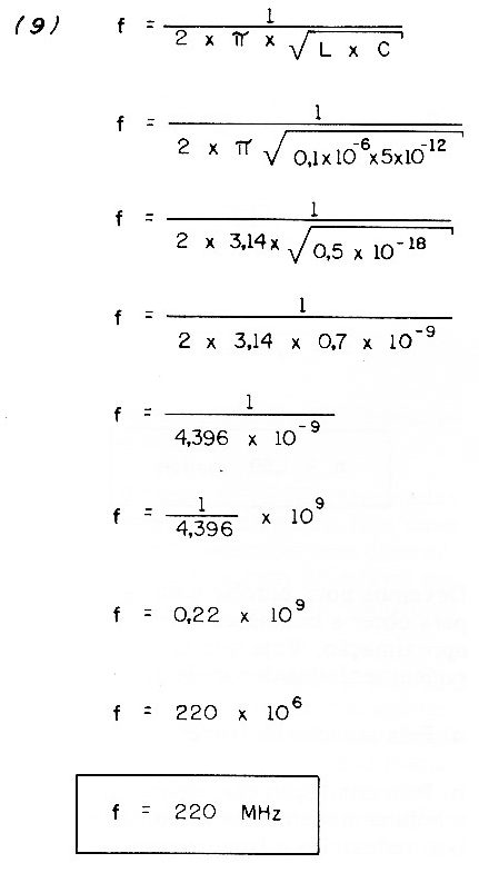
The theoretical upper limit of this circuit, taken as an example, is therefore 220 MHz. In practice, this is not enough, as the parasitic capacitances and the inductances of the connecting wires must always be considered.
The reader must see that we can still work with a slightly different type of calculation, always based on the same formulas.
Be the following problem:
What happens to an LC resonant circuit if it is reduced the number of turns of a coil by 20%, for example, from 5 turns to 4 turns. That would be the case if you want to convert an FM receiver into a VHF receiver. See Figure 7.
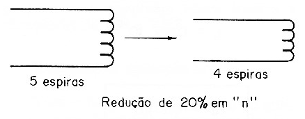
We then start from the expression (10)

In this we have the basic inductance for the normal values ??of n, S and I. As we are going to take 20% of the turns, we change n to 0.8 x n, that is, we are left with 8 tenths of n, the value we apply in the new formula, given in (11).

To determine what happens to the inductance, we must then divide one expression by another. That is, we calculate the result of L / L1, which leads us to development (12)
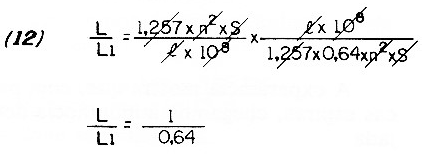
By making the necessary cancellations, we are left with:
L / L1 = 1 / 0.64
Interpreting this result, we observe that the removal of 20% of the turns causes a reduction of 36% in the inductance, that is, it is reduced to 0.64 of the original value (disregarding the consequent changes in length).
Passing these values to the frequency we have the expression (13)
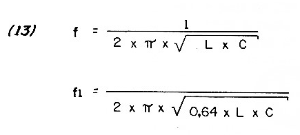
We also do the same.
Where:
We calculate f (frequency) for normal values ??of L and C and then we calculate the new frequency (f1) for the changed value of 0.64 for L. Dividing the expressions member by member, we have the result in (14).
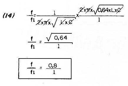
Then see that, for the result, we obtain that the frequency "rises" from 0.8 to 1, which means an increase of 20% in its value.
The conclusion is simple:
The proportion of turns that we remove or add to a coil, as long as it does not influence much in its length, is directly reflected in the frequency of the circuit. If we remove 10% of the turns, the frequency increases by 10%.
It is clear that these values are for the purpose of approximation in an experimental work, since we have to take into account that the removal of turns always affects the length of the coil, as well as any parasitic capacitances.
Another problem
How does the presence of a core influence the resonance frequency of an LC circuit?
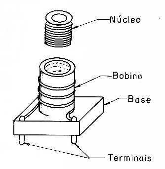
The introduction of a ferrocart core in a coil increases its inductance, as shown in formula (15).

The presence of the core has the effect of concentrating the lines of force of the created magnetic field, with the consequent increase in inductance. See the increase in inductance, and consequently the decrease in frequency, can be analyzed as follows:
As we can see from the formula, the permeability coefficient of the core appears multiplying the expression that gives the inductance of the coreless coil.
Thus, if the core is made of material with a permeability coefficient 2, for example, the inductance will be multiplied by 2.
As the frequency depends on the inverse proportion to the square root of the inductance, it is easy to see that the frequency will change in the case of a factor equal to the square root of 2, that is, 1.41.
Thus, placing a material with a permeability of 2 in the core of a coil, the frequency will be lowered by approximately 1.41.
In the case of a 100 MHz circuit, this frequency will drop to 70.92 MHz.
Note that the possibility of moving the core inside the coil is very important when you want to adjust the circuit over a wider range.
As the presence of the core allows the frequency to be changed in a relatively wide range, we can perfectly replace the trimer with the adjustable core, with advantage, connecting in parallel a fixed capacitor of determined value according to the desired limits.
The example of a core with a 1.41 factor for frequency change shows that we can have a very wide adjustment range. With the entire core out of the coil, the circuit will be tuned to 100 MHz. With the entire core inside, the circuit will be tuned to 70.9 MHz. This corresponds to a band almost 30 MHz wide!
Conclusion
Coils with adjustable cores, such as from TOKO, can be obtained in inductance bands which are suitable for operation in circuits from low frequencies (medium waves, for example) to FM and VHF.
With the use of these coils, it is even easier to design receivers and transmitters.
Of course, the experimenters will have cases in which they will need to build these coils themselves, but with the suggestions given, this will be much easier.
Remember that working with RF circuits is a little different from working with conventional electronics in which it is assembled and operated! In RF, it is necessary to be patient, mainly to reach the ideal points, with the adjustment of each resonant circuit individually, and in a very critical way.


