There are many differences between an electric diagram and an electronic diagram. These differences start with the symbols used to represent components and end with the way they are connected. These differences are one of the problems to be solved by an electrician wanting to know something about electronics.
He needs to be acquainted with new symbols since there are many electronics components represented by symbols that the electrician doesn't know. Learning the symbols used to represent each component and what they do in a circuit are the next steps in this site.
Let's begin with the schematic diagrams.
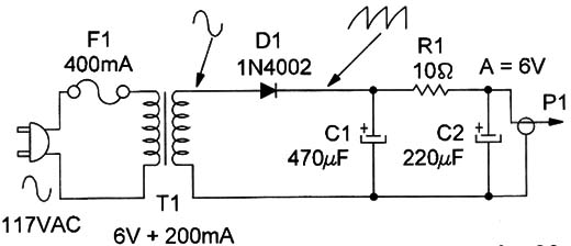
Figure 1 is a diagram of a simple piece of electronic equipment: a DC power supply similar to those used to power small calculators, CD players, and other appliances from the AC power line.

This schematic diagram represents all components by their symbols, and in many cases, the identification, values, and other important information are given. At the side of the symbol of each component is the identification number. This is important since it can help the technician find the component on the PCB or inside the equipment.
For example, all the resistors are identified by the letter R followed by the number of the device in the equipment. This means that many resistors can be found in a device identified by R1, R2, R3, etc. Capacitors are usually noted by the use of the letter C.
The capacitors of a circuit are numbered starting from C1, C2, C3, etc.
Transistors can be identified by the letters Q, T, or TR. They can be represented as Q1, T1, or TR1.
ln many cases, a second number can identify the “block” or a “stage” in which the component is placed. So, the resistors of the first stage can begin at R101 and the resistors in the second stage from R201. Near the identification and the symbol we can also find the value or type of the component.
Resistors have the value of resistance to the side, such as R1, 1000 Ω or 1k. If it is a transistor, you might find 2N3906, meaning that when used, the transistor must be replaced with a 2N3906. The usual identification number for transistors begins with a 2N, but many manufacturers have started using letters signifying their names such as TIP (Texas Instrument) and MPS or MM (Motorola).
There is also a European code that uses the letters BC or BD in the identification of devices, and a Japanese configuration that uses the letters 2SB, 2SC, or 2SD to indicate transistors.
Depending on the circuit, other important information can be found in the schematic diagram. For example, the voltage at different points in the circuit can be found.
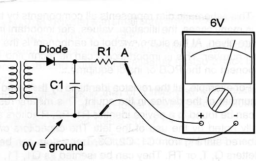
In the example presented, it is indicated that, between A and the ground (normally taken by reference or 0 V), the measurement is 6 V when a multimeter is used to take the voltage (Figure 2).

Another important piece of information found in a diagram is the wave-form of the signal present in a point.
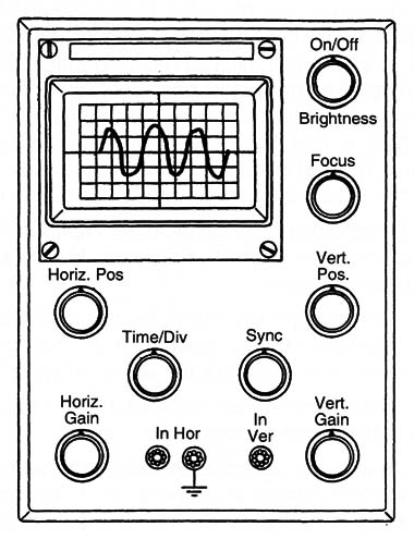
As we said, electronic circuits don't operate only with DC voltages but also with AC voltages in a large range of frequencies and waveforms. These AC voltages or signals are not only sine signals, but can have several waveforms and amplitudes. Oscilloscopes are used to observe waveforms of a signal in a circuit.
Figure 3 shows a common oscilloscope used on electronic workbenches for troubleshooting and diagnostics.

By observing the waveform of a signal at a point in a circuit a technician can determine what is wrong. The oscilloscope is one of the most powerful tools in the electronic lab. In the schematic diagram example there is the indication of a waveform at point A when C1 is open and D1 in short.
Also found on a schematic are procedures for installation, diagnostics, equivalence, etc. Diagrams for many types of equipment can be found with their manuals, but this is not common. A solution for the electrician who has problems with a piece of equipment and needs the schematic diagram is to purchase one.


