An electric motor is basically formed by windings and therefore a magnetic circuit which presents a certain inductance.
Unlike pure resistive circuits, such as filament lamps (incandescent), heaters, etc., an inductive circuit with similar properties to those of engines: absorbs two types of energy.
One energy is called "active" which is utilized to perform a mechanical work such as moving the set of gears of a machine.
The other energy is called "reactive" and is not reused, serving only to produce the magnetization of the magnetic material that is in the engine and is responsible for its operation.
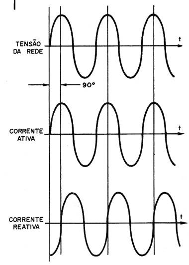
The two energies come from the grid, in which case manifests itself as an alternating current of 60 Hz. However, the behavior of the engine is such that the current of active and reactive power does not keep the same phase (Figure 1).

While the current that corresponds to the active energy is in phase with the voltage which powers the circuit, the reactive current is 90 degrees apart.
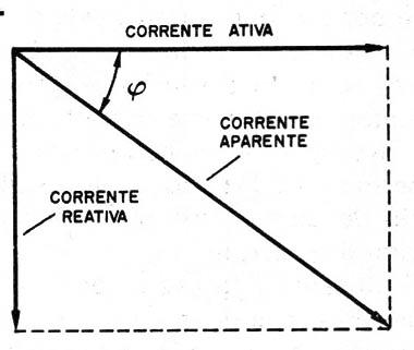
The result is that the engine which operates according to this principle, with no additional resource, is driven by an apparent current corresponding to the vector composition of the two currents analyzed.
In fact, this current is not so apparent as the name implies, for the energy turnover of a company which uses engines is done in its function.
As we can see in Figure 2, if the active component of an engine is too great regarding the reactive component, the apparent current will have a very close value of the active component.

We can say that in this case, the engine will be using the energy it receives very well.
On the other hand, if the reactive component is too great regarding the active component, the apparent current will be much bigger than the active component, which means we will be paying more than we will be using.
In short, it is important to keep the reactive component as small as possible, or the angle φ as close to zero as possible.
In practice, we do not really speak in terms of angle, but in "power factor" which is measured in the form of the angle ? cosine.
COSφ = Iactive / Iapparent
In theory, the ? cosine may range between 0 e1 (the angle varies between 0 and 90°), but in practice the values lie around between 0 and 80° for the angle.
In practice, we must maintain the ? cosine as close to 1 as possible, so we can pay for the energy we actually use.
A table can give us an idea of the different values of this cosine, and what happens when they are being observed:
| Cosφ | Condition |
| 0.2 to 0.4 | Motors with bad installation |
| 0.4 to 0.7 | Motors with bad utilization |
| 0.7 to 0.9 | Motors with good utilization |
| 1.0 | pure resistive circuits |
How to correct the power factor? The capacitors have an "opposite" feature to the inductors, responsible for the reactive current.
While the inductors advance the current in relation to the voltage, the capacitors delay.
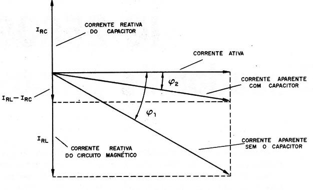
If in an inductive circuit, we put an appropriate value capacitor, the reactive current which the capacitor is responsible tends to oppose the reactive current of the magnetic circuit, as shown in Figure 3.

The result is a reduction of the angle ? and consequently an increase of the cosine of ? with the approximation of the apparent current of the active current value, which improves the system performance.
The commercial engines already come with capacitors carefully calculated to make this compensation, but if for any reason this capacitor gets damaged, the problem may appear with an exaggerated motor consumption which reflects in the light bill.
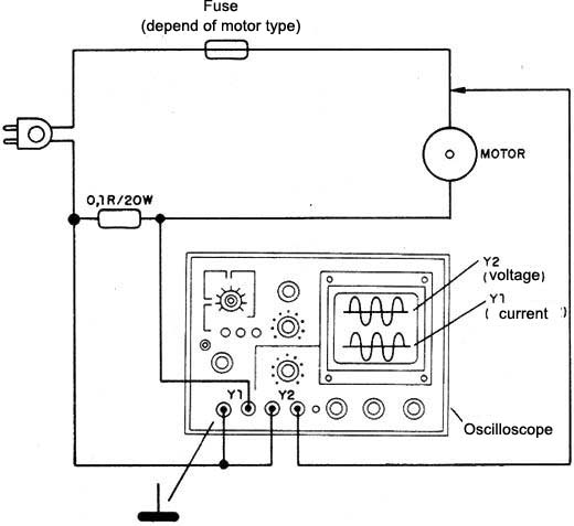
In Figure 4 we have a circuit that allows the use of a dual trace oscilloscope in the check of the power factor.

Note the connection of the earth common point which must be well done to avoid damages to the instrument or shock hazards.
With this procedure we can see the gap which exists between the voltage and the current, and thus determine the power factor.
For those operating with many equipment gifted with motors, the use of a power factor meter or the cosine of φ is much more comfortable.


