You can use the device as an emergency light, in trailers, for signaling, and so on. The current drain depends on the characteristics of the lamp, and the transformer and can range from 100 to 800 mA.
The lamp brightness will depend on the drained current. Experiments should be done with several transformers and oscillator frequencies to get the best performance.
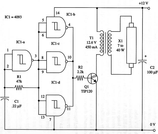
The circuit is formed by a low-frequency oscillator (IC1-a) that drives a buffer formed by IC1-b, c, and d. The buffer drives a Darlington power transistor whose load is a small transformer.
High Voltage is obtained from the transformer to light the fluorescent lamp.
You can alter the frequency of the oscillator by changing R1 and C1 to find the appropriate light level. If desired, you can replace R1 with a 100 k Ω potentiometer ín series with a 10 k Ω resistor. This will allow frequency adjustment to obtain better performance.
A schematic diagram of the FIuorescent Lamp Inverter is shown in figure1.

Transistor Q1 must be mounted on a large heatsink. T1 is a 12.6 V, 450 mA transformer. Radio Shack 273-1375 is suitable for this project but, because it has a CT transformer, you should use only two of the three secondary wires. You can experiments with a transformer with secondary currents ranging from 300 to 800 mA and Voltages between 9 and 15 V for better performance.
You can also increase the power output by replacing Q1 by a power FET. Any power FET rated to 2 A or more can be used in this circuit.
The IRF640 ís suitable for this task.
The fluorescent lamp is rated from 7 to 40 W, and even lamps that will not function on the ac power line can be used.
Warning: the fluorescent lamp is powered with dangerous high voltage. Be careful with wire insulation and device connections.
IC1 - 4093 CMOS integrated circuit
Q1 -TIP120 NPN Darlington power transistor
X1 - FIuorescent lamp, 7 to 40 W (see text)
T1 - 117 Vac/12 Vac, 450 mA transformer (see text)
R1 - 47,000 Ω, 1/4 W, 5% resistor
R2 - 2,200 Ω, 1/4 W, 5% resistor
C1 - 0.22 pF metal film or ceramic capacitor
C2 - 100 µF 16 WVDC electrolytic capacitor


