All you have to do is change Cl by units ranging from 47 to 1,500 µF.
The circuit can power lamps from 200 mA to 1 A and is supplied from 6 to 12 V supplies, depending on the lamp you intend to use.
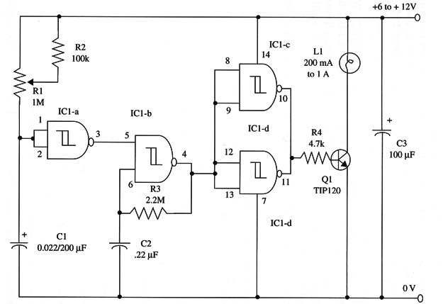
The flash rate is given by R3 and C2, and the rate is about 1 Hz. You can also change this rate varying the value of C2 or replacing R3 with a 2.2 M9 potentiometer with a 100 kg series resistor.
To add a start switch, place an SPST switch in series with Cl. When this switch is turned on, capacitor Cl begins to charge, and IC1-b the oscillator is turned on. The lamp is then powered, producing flashes of light. When Cl is charged, ICl-a output goes low, ICl-b oscillator stops, and the lamp goes out.
A schematic diagram of the Delayed Turn-Off Flasher is shown in Fig. 1.

Suggestions for the lamps are given in other projects in this section. Transistor Q1 must be mounted on a heatsink. The proper position of the polarized components must be observed.
You can increase the power output replacing the output transistor by using any power FET with current ratings of 2 A or more.
lC1 - 4093 CMOS integrated circuit
Q1 - TIP120 NPN Darlington power transistor
L1 - 200 mA to 1 A incandescent lamp, 6 to 12 V (see text)
R1 - 1,000,000 Ω - potentiometer
R2 - 10,000 Ω, 1/4 W, 5% resistor
R3 - 2,200,000 Ω, 1/4 W, 5% resistor
R4 - 4,700 Ω, 1/4 W, 5% resistor
C1 - 100 µF/220 µF, 16 WVDC electrolytic capacitor
C2 - 0.22 or 0.47 µF ceramic or metal film capacitor
C3 -100 µF, 16 WVDC electrolytic capacitor


