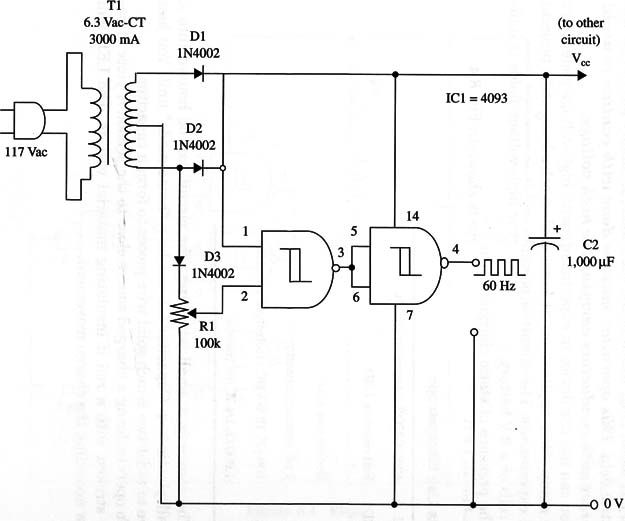
A schematic diagram of the 60 Hz generator is shown in Fig. 1.

Any transformer rated for 5 to 12 V and currents ranging from 50 mA to 1 A (or as required by the project) can be used. The circuit can also be used to power any project driven by a 60 Hz generator- a clock, for instance. R1 is adjusted to give the required output. An oscilloscope can be used to adjust the circuit.
IC1 4093 CMOS integrated circuit
T1 6.3 V, 300 mA transformer (see text)
R1 100,000 9 trimmer pot
Cl 1,000 µF, 25 WVDC electrolytic capacitor
D1, D2 1N4002 or equivalent silicon rectifier diodes


