The circuit can control loads up to 1 A With a mini relay (Radio Shack 275-249), or heavy-duty loads With a 10 A mini relay (Radio Shack 27 5-2488).
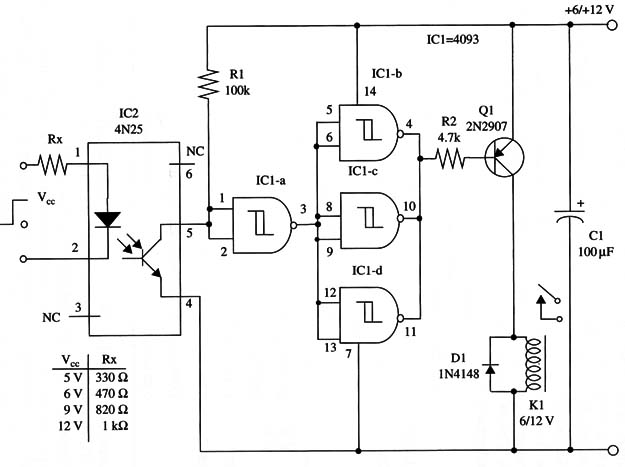
The circuit turns on the load With a high logic level at the input, and Rx is used to limit the current How through the LED, according the digital output signal. The table Within the schematic diagram shows Rx values as function of output voltage (Vec). The circuit can be powered from 6 to 12 V supplies, depending on the relay.
A schematic diagram of the Opto-Coupler Interface is shown in Fig.1.

The circuit can be mounted on solderless boards or printed circuit boards, and layout depends on the relay employed and the size and shape of other components. Proper polarity of the input Wires must be observed.
IC1 4093 CMOS integrated circuit
IC2 4N25 or equivalent opto-coupler
D1 1N4148 general purpose silicon diode
Q1 2N 2907 PNP general purpose silicon transistor
K1 6 or 12 V relay (see text)
Rx See text
R1 100,000 ohm, 1/4 W, 5% resistor
R2 4,700 ohm, 1/4 W, 5% resistor
Cl 100 µF, 16 WVDC electrolytic capacitor


