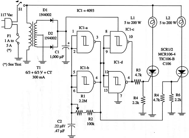
Note that this is a half-wave circuit, so the lamps will flash with half the rated power. This factor should be considered in determining appropriate circuit applications, which include warning systems, decoration, and so on.
The frequency range can be altered by changing C2 values. Values can range from 0.22 to 10 µF. The circuit can easily drive two 200 W lamps. The SCRs must be mounted on heatsinks.
A schematic diagram of the Twin-Lamp AC Flasher is shown in Fig. 1.

Special care should be taken with the high-current and high-voltage lines. The circuit can be housed in a plastic box with all the high voltage lines completely isolated from external touch.
Proper positioning of the polarized components as the diodes, electrolytic capacitors and the SCRs must be observed. SCRs rated to 200 peak inverse voltage (PIV) or more can be used in this project.
The fuse is chosen according the lamps used. An 1 A fuse is em- ployed with 5 to 40 W lamps, a 2 A with 60 to 100 W lamps, and a 5 A fuse with lamps rated from 120 to 200 W.
IC1 4093 CMOS integrated circuit
SCRl, SCR2 TIC106, MCR106, or C106 SCR, 200 V peak inverse voltage (PIV)
D1, D2 1N 4002 or equivalent (50 V, 1 A) silicon diodes
T1 6.3 V, 300 mA CT transformer, primary 117 Vac (see text)
F1 1 to 5 A fuse, depending on the lamp
S1 SPST toggle or slide switch
L1, L2 5 to 200 W incandescent lamp, 117 V
R1 2,200,000 ohm potentiometer
R2 100,000 ohm, 1/4 W, 5% resistor
R3, R5 4,700 ohm 1/4 W, 5% resistors
R4, R6 2,200 ohm, 1/4 W, 5% resistors
C1 1,000 µF, 25 WVDC electrolytic capacitor
C2 0.22 µF to 0.47 µF ceramic or metal film capacitor


