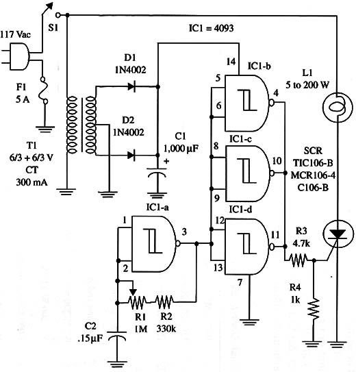
The circuit can drive 5 to 200 W incandescent lamps, and the effect is adjusted by R1.
A schematic diagram of the Flickering-Flame Effect is shown in Fig.1.

The SCR must be mounted on a heatsink. Proper positioning of the polarized components must be observed.
IC1 4093 CMOS integrated circuit
SCR TIC106, MCR106, or C106 (200 PIV) silicon controlled rectifier
D1, D2 1N 4002 silicon rectifier
T1 6.3 V, CT, 300 mA transformer, primary 117 Vac
F1 5 A fuse With holder
S1 SPST toggle or slide switch
R1 1,000,000 ohm potentiometer
R2 330,000 ohm, 1/4 W, 5% resistor
R3 4,700 ohm, 1/4 W, 5% resistor
R4 1,000 ohm, 1/4 W, 5% resistor
C1 1,000 µF, 25 WVDC electrolytic capacitor
CZ 0.15 µF ceramic or metal film capacitor
L1 5 to 200 W incandescent lamp (117 Vac)


