(*) The article is part of my book Electronic Projects from the Next Dimension (Newnes – 2001) and was also published in a Brazilian Magazine.
The circuit also includes a modulation stage. This stage, when activated, will turn the ultrasonic source on and off at regular intervals. Some experiments can be programmed using this effect.
As the output stage has a low impedance, it is not necessary to remove the transformer from the tweeter. Therefore, the transducer can be. plugged directly to the output of the circuit.
Ultrasonics are dangerous to small mammals, as many of them can hear sounds up to 40,000 Hz (dogs, cats, rats, mice, etc.). A high-power ultrasonic source can cause severe discomfort in these animals, so avoid the use of this oscillator in places where they reside.
Note: This circuit can be used to scare rats, mice, and other mammals from trash areas and other places where they congregate.
Operation
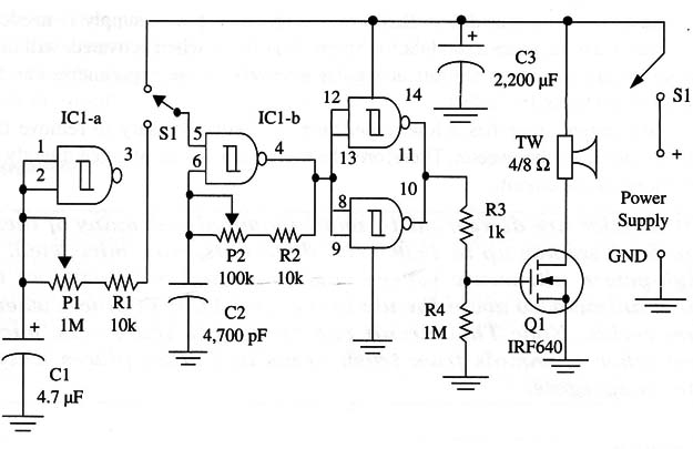
The circuit operates in the same manner as other described in this site. We have only added a power output stage using a power FET, plus a low-frequency oscillator. The use of a power MOSFET adds to the circuit the capability of driving a low-impedance load from the signal found in the output of the digital amplifier using the 4093.
The additional stage is a low-frequency one, using one of the four NAND gates of a 4093 IC. Pl adjusts the modulation rate and P2 the ultrasonic frequency.
Assembly
The complete circuit of the high-power ultrasonic source is shown in Fig. 1.

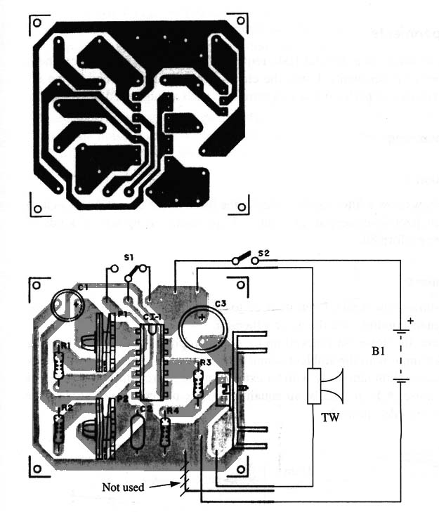
The components are mounted on a small printed circuit board as shown in Fig. 20.

Any power FET can be used in this circuit. Types with drain currents above 2 A and voltages above 100 V are suitable.
Q1 must be mounted on a heatsink. The heatsink can be simply a piece of metal bent to form a “U” or any commercial type as shown in the figure and affixed by a screw to hold the transistor in place.
A plastic box can be used to house the components. The tweeter can be placed outside the box. A cable with plugs can be used to plug the circuit to the power supply.
The transformer has a secondary Winding with 12 to 15 V >< ] A, and the diodes are 1N4002 or equivalents.
Using the Circuit
The circuit is used in the same manner as the previous one. See the suggestions for experiments at the end of this chapter. If Q1 tends to heat excessively, wire a 10 ohm x 5 W resistor in series with the tweeter.
Semiconductors
IC1 4093, CMOS integrated circuit
Q1 IRF640 or any equivalent (see text)
Resistors
R1, R2 10 kΩ, 1/8 W, 5%-brown, black, orange
R3 1 kΩ, 1/8 W, 5%-brown, black, red
R4 1 kΩ , 1/8 W, 5%-brown, black, green
Capacitors
C1 4.7 µF/ 12 W Vdc electrolytic
C2 4,700 pF, ceramic
C3 2,200 pF, 25 W Vdc, electrolytic
Miscellaneous
P1 1 MΩ, potentiometer
P2 100 kΩ, potentiometer
TW 4/8 Ω, piezoelectric tweeter
S1 DPST, toggle or slide switch
S2 SPST, toggle or slide switch
Printed circuit board, heatsinks, fuse holder, power cord, wires, solder, plastic or
metallic box, plastic knob, etc.


