This circuit was originally published in a Brazilian magazine and included in my book Electronic Projects from the Next Dimension (Newnes – 2001). The circuit operates only with analog TV.
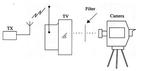
The noise produced by this circuit can be used in experiments to pick up the images using a camera and the TV as shown in Fig. 1.
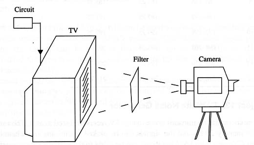
When picking up images from a TV using a camera, the reader must take into consideration the beat phenomenon that occurs due to the different sweep frequencies of the two devices.
This means that when the TV is producing one line on the screen, the camera is registering another line. This difference in synchronization causes the images recorded from a computer monitor or other TV set to be chopped when reproduced.
Consider this fact when editing the image frame by frame.
How It Works
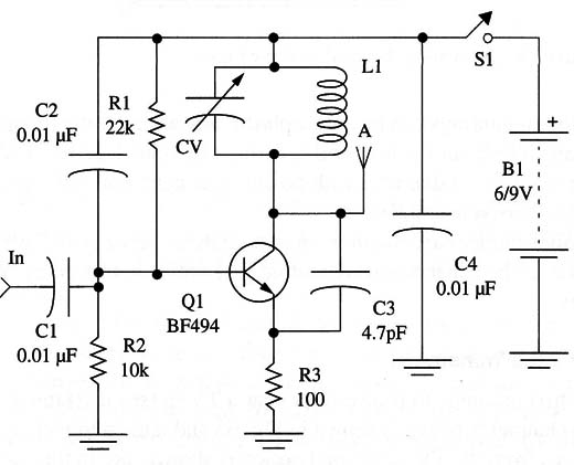
The transmitter is a simple low-power VHF oscillator using an NPN RF silicon transistor. The transistor is wired in the common base configuration. L1/CV form the resonant circuit determining the frequency of operation of the transmitter.
With the coil indicated in the project, the circuit will oscillate between 54 and 88 MHZ, corresponding to channels between 2 and 6, but the coil can be altered to make the circuit oscillate between 174 and 216 MHZ, corresponding to channels 7 to 13. See in the suggestions how to make this alteration.
Bias is given by R1 and R2 and feedback by C3. The noise is applied to the base of the transistor by Cl. Any of the noise generators described in this site can be used as signal source to modulate this transmitter.
It is important to see that the level of noise determines how the signal produced by the transmitter spreads by the channel band. If enough noise is applied to the input, the transmitter will also produce noise in the audio band, allowing the experimenter to perform recordings in the audio band of the tape.
Parallel experiments with EVP can be performed this way.
The power supply is formed by four AA cells or a 9 V battery. Since power consumption is not high, a 9 V battery can power the circuit for several hours.
The antenna is a small piece of rigid wire 10 to 30 cm long. Do not use long antennas, as they may interfere with other TV sets in your neighborhood. Doing so can create severe problems with the FCC!
Assembly
A diagram of the TV transmitter is shown in Fig. 2.
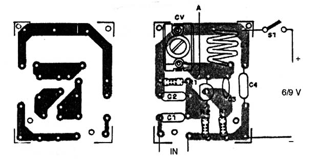
The transmitter can be mounted on a small printed circuit board as shown in Fig. 3.
Since the circuit is not critical, mounting can also be accomplished using a small terminal strip as shown in Fig. 4.
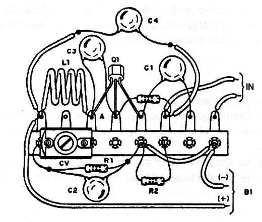
Equivalents of the specified transistor can be used, such as the 2N2222 or 2N2218. But observe that the terminal placement is different from the original.
Both mountings can be placed inside a plastic box with a jack for the input signal and a hole for the antenna. The coil is formed by four turns of 22 or 24 AWG bare wire with a diameter of 1 cm with no core (air core). This coil will produce signals between channels 2 and 6.
Any trimmer capacitor with maximum capacitances between 15 and 50 pF can be used. The capacitors indicated as ceramic types must not be replaced by other types.
Using the Transmitter
The first option is to place the transmitter near a TV receiver (see text) tuned to a free channel between 2 and 6, as shown in Fig. 65 and use a camera to pick up the images from the TV screen. The second option is shown in Fig. 5.
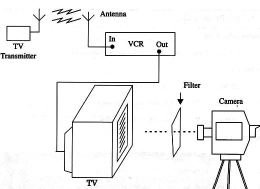
In this case, a video cassette recorder is used as tuner and placed near the transmitter. The Video cassette is adjusted to a free channel between 2 and 6. In both cases, adjust CV to select the signal from the transmitter making the recordings.
WARNING: Do not tune the circuit to the frequency of channels that are in use in your location. The transmitter will interfere with any TV placed near the transmitter when tuned to the same channel.
Be sure that, in the channel you are using to pick up the images, there is no signal from distant stations. A weak signal superimposed on the noise can be confused as a “paranormal” image. You would not like to have the face of your favorite TV show's announcer included in a next-dimension photo! unplug the external antenna to avoid these signals.
Suggestions
Use a two-turn coil and replace C3 with a 1 pF capacitor. The transmitter will produce signals between channels 7 and 13.
A “gray” image can be produced if the noise source of the circuit is disabled.
Some experiments can be performed using this image. In this case, the circuit will generate only a pure video carrier, filling the screen With a uniform image. The brightness and contrast can be adjusted using the TV controls.
If a sound source (audio oscillator or the output of a tape recorder With an EVP tape) is plugged into the input of this transmitter, it will modulate the image with unexpected effects that can be used in experiments.
A low-frequency oscillator plugged to the input of the transmitter will produce horizontal bars on the screen. They can be used in experiments.
Semiconductors
Q1 BF494 or equivalent RF NPN silicon transistor
Resistors
R1 22 k ohm, 1/8 W, 5%-red, red orange
R2 10 k ohm, 1/8 W, 5%-brown, black, orange
R3 100 ohm, 1/8 W, 5%-brown, black, brown
Capacitors
C1 0.01 pF, ceramic or metal film
C2 0.01 pF, ceramic
C3 4.7 pF, ceramic
CV Trimmer capacitor (see text)
Miscellaneous
L1 Coil (see text)
S1 SPST, toggle or slide switch
B1 6 or 9 V, four AA cells or one 9 V battery
A Antenna (see text)
PCB or terminal strip, plastic box, battery clip or holder, Wires, solder, etc.


