This article was originally published in a Brazilian magazine and translated into English to be part of my book Mechatronics for the Evil genius – TAB 2005.
The basic version of an electromagnet described here can be used in many experiments and practical applications. Only two components are used in this very inexpensive project. It is a project recommended to the readers who want to experiment with electromagnetism and need something very easy to build and use. Other versions, including a horseshoe electromagnet, will be described later.
Objectives
Mount an experimental electromagnet.
Learn how it works.
Understand how some applications that use electromagnets work.
Mount some mechatronic projects that use electromagnets.
The Project
The circuit works based on a discovery made in the nineteenth century by the Danish professor Hans Christian Oesterd. Oesterd discovered that when an electric current flows through a wire, a magnetic field appears around the wire. More details about Oesterd’s discovery can be found in the previous project on the experimental galvanometer.
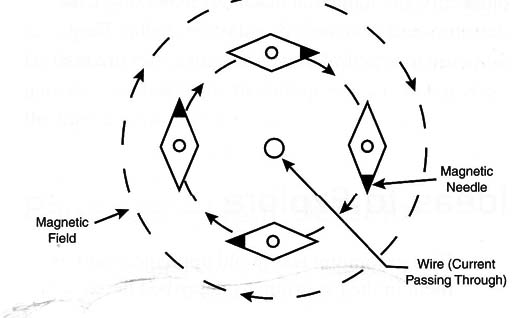
In few lines we can say that if a large amount of current flows through the wire, the field will be strong enough to move the needle of a compass, placing it perpendicular to the wire, as shown in Figure 1.
The next step in his discovery was to demonstrate that the magnetic field could be concentrated if the wire is used to form a coil. Flowing through a coil an electric current can produce a strong magnetic field inside it. Figure 2 shows that the field is stronger inside the coil.
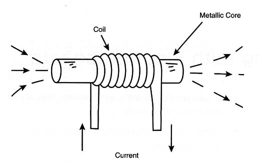
Metal pieces placed at the center of the coil will remain magnetized, attracting small pieces of metal.
But the interesting fact to be observed in this experiment is that the magnetic field exists only during the time in which the current is flowing. As long as the current is cut, the magnetic field disappears and no more attraction is observed.
Our simple project consists of a small electromagnet powered from a D cell. The field is strong enough to attract small metal pieces in demonstrations or even some interesting mechatronic applications.
BuiIding the Electromagnet
The circuit is very simple: Only two components are needed. Figure 3 shows the schematic diagram of the electromagnet.
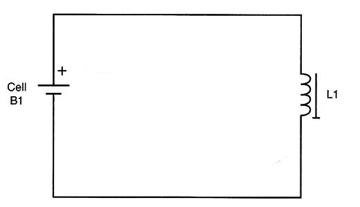
Figure 4 shows the components used in this project and how they are wired.
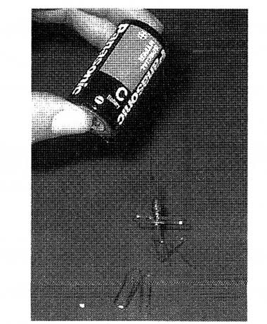
The electromagnet is made by Winding 100 to 500 turns of any 28 to 32 gauge enameled AWG wire around a small nail or screw. Any iron nail or screw from 2 to 3 inches long can be used.
You must uncover the wire using a wire cutter, pocketknife, or other tool. The enamel is an isolator that will not allow the electricity to flow from the wire to the poles of the cell.
The power supply is a D cell; the electromagnet circuit drains a large amount of current, and AA cells will run down quickly if used.
Test and Use
Using the electromagnet is very simple: Place the ends of the wire in contact with the cell's poles. Verify that the cover of the wire has been removed at the point where it will contact with the cell so that the current flows. Remember that putting the electromagnet near small pieces of metal will attract them.
Don’t use the electromagnet for extended periods of time. If the current flows through the coil for periods of time longer than a few seconds, the current will produce heat in the coil and damage it. Turn the electromagnet on and off in short spurts, only for the demonstrations.
Electromagnet
B1 D cell (see text)
L1 Electromagnet (see text)
Exploring the Project - Other Versions
Figure 5 shows how to improve the performance of the electromagnet or to alter it using other formats and materials.
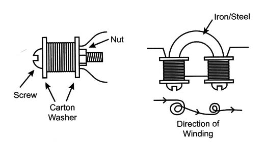
Powering from a Different Power Supply:
If your electromagnet is powered by a 3- to 6-volt power supply, add a 22-ohm x 1-watt resistor in series with the electromagnet. This resistor will limit the current flow through the coil, avoiding overheating.
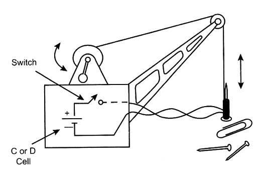
Building e Crane
A mechatronic project using the electromagnet is shown in Figure 6. The PWM control can be used to control the speed of the up and down movement of the electromagnet. The S1 switch is used to catch or release objects.
The Bottle's Challenge
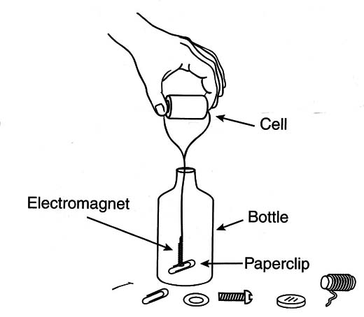
Use this as a fun intelligence test you can give to your friends or parents. Put an empty bottle on a table with a metallic paper clip or a piece of metal (a nut or a screw, for instance) inside the bottle. Spread across the table small objects, such as a pencil, a piece of paper, a spoon, drinking straws, a small nail, 3 meters of enameled wire (28 to 32 AWG), coins, paperclips, cotton swabs, wooden matches, a D cell, and so on.
The challenge is to extract the object inside the bottle without moving or touching the bottle. The bottle can't be turned upside down and it can,t fall from the table.
Of course, one of the first ideas that occurs to the person is to build some kind of hook using paperclips, attaching them to the wire, and trying to catch or hook the object in the bottle.
After many unsuccessful tries, the individual will be surprised when you simply wind the wire around the nail, grasp the ends of the wire to create a good electric connection, and connect it to the cell, making a magnet. Inserting the magnet into the bottle, the object will be attracted and be pulled easily to the opening, solving the problem. Figure 7 illustrates this being done.
Experiments and Upgrades
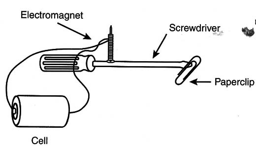
Show that magnets attract only certain kinds of metals. They can't attract metals such as copper or aluminum. Explain why paper, glass, plastic, and other materials are not attracted by the magnets. Figure 8 shows a simple experiment to demonstrate the process of magnetization by induction. When the electromagnet is powered on, you will be able to attract a paperclip using the screwdriver.
Controlling the Power
You can control the amount of power in your magnet by using two circuits described in this book. The first uses an electronic potentiometer (ART084E) wired in series with the electromagnet. Power the circuit with a 3- to 6-Volt power supply and then add 10-Ω x 1-watt resistor to limit the current, as shown in Figure 9.
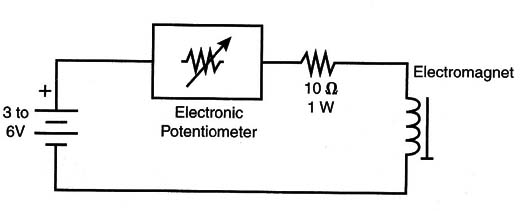
The second circuit that can be used to control the power applied to the magnet is the pulse width modulation (PWM) control (see MEC027Es). In this case, you also have to limit dhe current by using a resistor (10 Ω x 1 watt).
Figure 10 shows another circuit where the power source is being controlled. It has a constant current source using an LM350T IC.
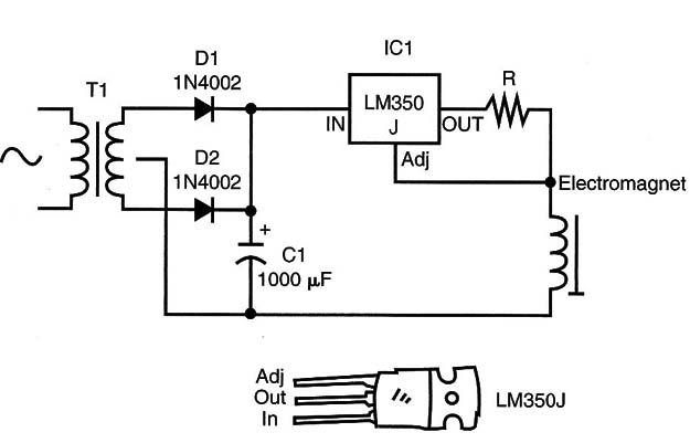
Typically, R can be calculated for source currents in the range of 50 to 500 mA to a magnet according to its size and the power needed. To determine the current, you only have to divide 1.25 (the internal reference of the IC) by the current you need.
For instance, if you want to power the magnet described here with 100 mA (a recommended current for the project), R must be as follows:
R : 1.25/0.1 (100 mA : 0.1 A)
R = 12.5 ohm
Use a 12.5 x 2-watt resistor. You can use the LM350T to source currents of up to 3 A, but with more than 200 mA the device must be placed on a heatsink.
Figure 11 shows how to mount a constant current source using a terminal strip as the chassis.
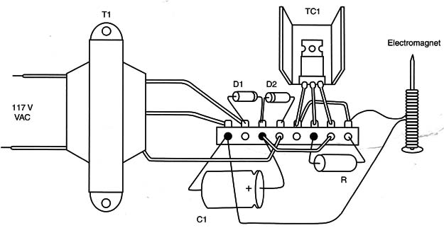
Constant Current Source
IC1 LM350T
D1, D2 1N4002 silicon rectifier diodes
T1 Transformer: primary coil rated to
117 VAC; secondary coil rated to 7.5 7.5 volts or 9 + 9 volts x 1 amp
C1 1,000 µF x 16-Volt electrolytic capacitor
R Resistor, according the load current (see text)
Power cord, terminal strips, solder, wires, etc.
Changing the Poles
You can create an interesting experiment to show how the poles of an electromagnet can change by inverting the direction of the current in its coil.
The experiment is shown in Figure 12.
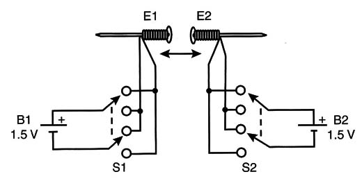
If the poles are opposites, the electromagnets will attract one another. If the direction of the current is changed in one of the poles, the poles will be the same and the electromagnets will repel one another.
The S1 and S2 switches are used to change the direction of the current, and the resistors are used to limit the current. Without the switches and resistors, the batteries will run down quickly, and the magnet will overheat.
Another Power Supply
Figure 13 shows how you can build a small power supply to power your experimental magnets and save your cells. The resistor is used to limit the current across experimental magnets, which tend to have low resistance and then drain large amounts of current.
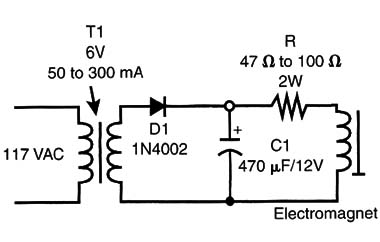
Using this circuit, your experiments will be safe and you can save your cells.
The power supply in this circuit is not regulated, and its voltage can change according the load. Therefore, this circuit is not suitable for electronic applications. You can, however, use it to power small motors, solenoids, and other appliances that are tolerant to a larger range of voltages.


