The amount of light (e.g., controlled by the shadow of your hand) falling on the light-dependent resistor (LDR) in this project will determine the tone produced by the circuit.
Extending your hand and keeping it over the LDR, you can control the tone produced by this circuit by letting more or less light fall on it. This is one of the applications for using this circuit as a feedback device.
This form of biofeedback can be used to help a person to concentrate his mind to keep control over the arm muscles for meditation. Other paranormal experiments are described below.
Experiments
Place the subject’s hand on the sensor, and use a light source to illuminate it as shown in Fig. 1.
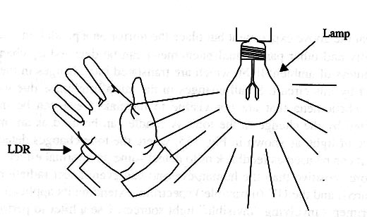
The hand isn't totally opaque, so some light can pass through it. The circuit can be adjusted to produce a tone from this light. Alterations in this tone indicate some modification in the blood flow in the hand, affecting its opacity.
Experiments With trance conditions and transcendental meditation, or during ESP sessions, can incorporate the detection of this physiological parameter using this circuit.
Place transparent and semi-transparent solid objects on the sensor and see if, using your mental power, you can alter the amount of light passing through them. This way, you can perform experiments involving PK.
A mirror at the end of a nylon wire and placed inside a transparent glass chamber can be used to detect paranormal skills as shown in Fig. 2.
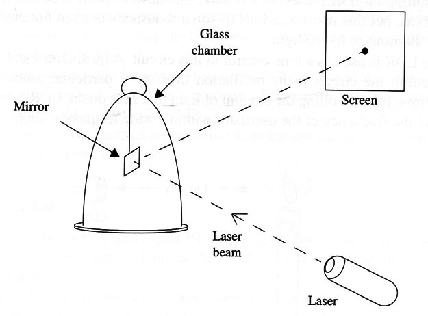
The person who is the subject of a PK experiment must move the mirror using his mind. A laser beam focused on the mirror and reflected to a screen forms a very sensitive movement detector.
Very small changes in the position of the mirror will produce a large displacement in the laser beam focused on the screen.
Repeat the above experiment but place the mirror on a pendulum.
Ghostly and other paranormal phenomena can be detected by changes in the brightness of ambient light, which are translated into changes in the tone generated by this circuit. Small changes in the lamp brightness due to “paranormal” phenomena that are not visible to the naked eye can be more easily detected by the change in the tone.
A candle can be used as an intermediate source of light, as shown in Fig. 3, where the tone changes detected by the circuit can be used as feedback or to detect some paranormal effect.
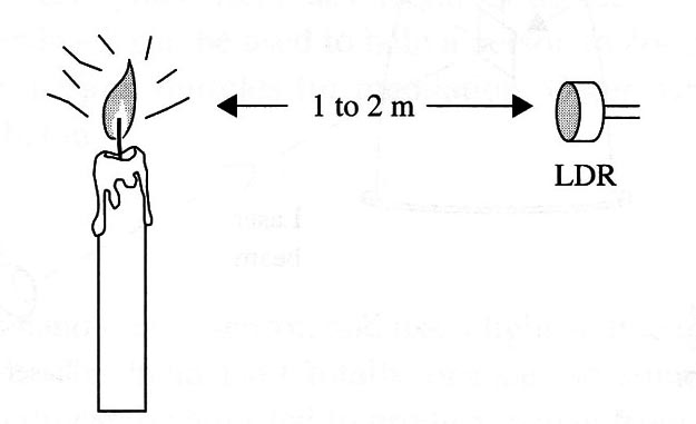
The circuit is more sensitive than the human eye and can even detect radiation in the IR (infrared) and the UV (ultraviolet) spectrum, extending its application to many experiments involving “invisible” light sources. Use a filter to perform experiments with specific light wavelengths.
Power for the circuit comes from two or four AA cells, and the unit can be placed inside a small plastic box. The reduced dimensions of this device allow it to be used in virtually any location.
How It Works
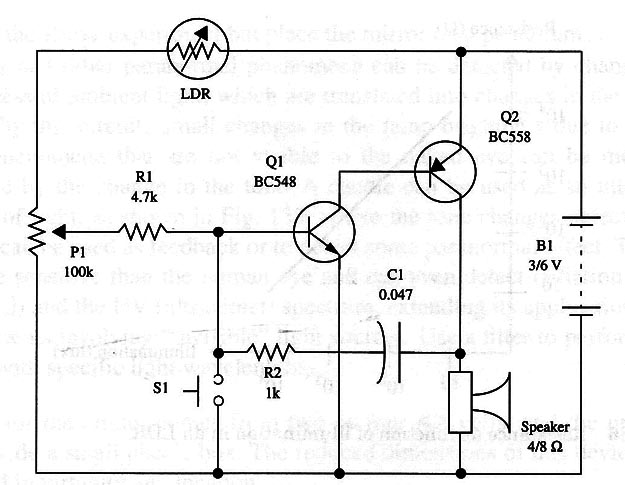
As is the case with many other circuits described in the Paranormal section of the site, this configuration is very simple. Two complementary transistors form a low-frequency oscillator.
The frequency is determined by Cl and the biasing network formed by the LDR, P1, and R1.
The LDR or a CdS cell is the light sensor in this circuit. When the sensitive surface of this device is exposed to light, its resistance changes.
As shown by Fig. 4, the resistance of an LDR decreases when the amount of light falling on it increases.
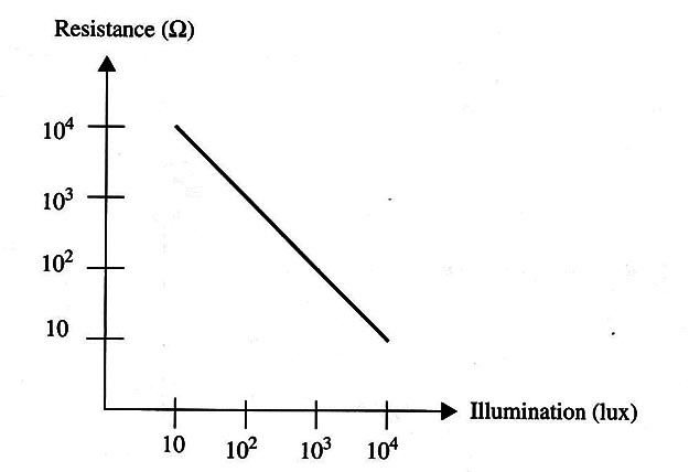
In the dark, this device shows a resistance of many megΩ, but this resistance falls to some thousands or even hundreds of Ω when illuminated by sunlight.
The LDR is used as a tone control in this circuit. Adjustments can be made via P1, setting the circuit to its oscillation limit by a particular amount of light.
Therefore, by controlling the amount of light that falls on the LDR, we are able to control the frequency of the oscillator within a wide frequency range.
Many components can be substituted in this circuit to alter its performance, as we will see in the suggestions.
S1 is used to cut the oscillation any time. You can also use a reed switch and operate it with a magnet, or use another kind of switch.
Assembly
Figure 5 shows the complete diagram of the light/dark controlled oscillator.
Because the circuit is very simple and not critical, it can be mounted on a terminal strip as shown in Fig. 6.
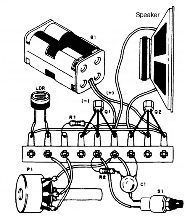
Keep the wires short to avoid introducing instabilities in the circuit. Any LDR can be used in this project. Types with diameter of 1 cm are suitable. You can increase the sensitivity by installing the LDR inside a cardboard tube and placing in front of it a convergent lens.
All the components can be installed in a plastic box. The size of the box depends basically on the loudspeakers diameter. Types with diameters from 5 to 10 cm are indicated for this application.
A power switch was omitted in this project, as the circuit can be turned off by removing the cells from the holder.
Using the Circuit
Turn on the power supply and adjust P1 until you obtain a tone with the ambient light.
Then place your hand in front of the LDR and see how its shadow can alter the tone frequency.
Biofeedback experiments can be performed by placing the circuit in any ambient and adjusting P1 to any tone. Then, placing your hands in front of the LDR, try not to maintain a steady tone.
Suggestions
Replace C1 with an 0.47 to 1 µF capacitor and adjust P1 to obtain spaced pulses.
You will then have a feedback metronome, and you can conduct some experiments using it. ln transcendental meditation and biofeedback experiments, you can adjust the metronome’s pulse rate to be the same as your heartbeat or your breath rhythm.
Place a color filter in front of the LDR to work with colored light sources. This way, the circuit will be able to detect light changes only in a specific color.
A second LDR can replace S1 in an experiment involving two light sources.
The circuit can be used to detect changes in an aura if the LDR is placed inside a cardboard tube with a convergent lens. Point the LDR at the aura and see how the tone changes.
The loudspeaker can be replaced with a headphone for some experiments.
Place the LDR inside a cardboard tube with a convergent lens in front of it to add directivity and sensitivity to the project.
Semiconductors
Q1- l BC548 or equivalent, any general-purpose silicon N PN transistor
Q2 - BC558 or equivalent, any general-purpose silicon PNP transistor
Resistors
R1 - 4.7 k, 1/8 W, 5% - yellow, violet, red
R2 1 k, 1/8 W, 5% - brown, black, red
Capacitors
C1 - 0.047 pF-ceramic or metal film
Miscellaneous
P1 - 100 k - potentiometer
B1 - 3 or 6 V, two or four AA cells
LDR - Any LDR or CdS cell (see text)
S1 - Pushbutton, normally open
SPKR 4 or 8 ohm x 5 or 10 cm loudspeaker
Terminal strip, cell holder, Wires, plastic knob for Pl, plastic box, solder, etc.


