Observation: this circuit was originally projected for exteriments in paranormal electronics for my book Electronic Projects from the Nex Dimension – Newnes 2001.
Experiments
Monitoring the temperature changes in living beings or inanimate objects can be important in many paranormal experiments.
Putting the sensor between your íingers, you can detect temperature changes by the movement of a meter*s needle. In a biofeedback experiment, you can then act in some manner to control it or make it move in the opposite direction. The sensor can be aflixed to other parts of the body as appropriate for the intended experiment.
Changes in the temperature of an object can also be monitored for experiments in PK and ESP. Use the sensor to detect if there are any temperature changes in an object you’re trying to move With your mind. You can also monitor temperature changes in an object that is observed or used as the target in an ESP experiment. Place the sensor on a plant's leaf to detect temperature changes in experiments involving PK and ESP.
In radiesthesia, the circuit can be used to detect small temperature changes in an object used as a sensor. This can be induced by the presence of water or mineralsor due the pendulum action.
Reaver is another area of experimentation in which this project can be useful. Temperature changes in the material to be bent can be detected during the experiments.
In transcendental meditation experiments, the sensor can detect when the skin temperature of a subject falls, indicating that the fourth state of consciousness or trance has been achieved.
Other paranormal fields include ghost or spirit manifestations altering the temperature of subjects (spontaneous combustion).
An important point to observe about this project is that the reduced thermal capacity associated with the small size of the sensor makes the circuit respond very quickly to temperature changes.
How It Works
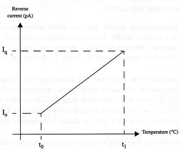
When a silicon diode is reverse-biased, the current flow or resistance depends on the junction temperature. More charge carriers are liberated in the junction when the temperature increases, reducing the resistance and increasing the current.
Figure 1 shows how the resistance of a reverse-biased diode changes with temperature. This property of a silicon diode (or any other device using silicon junctions) allows it to be used as a sensitive temperature sensor.

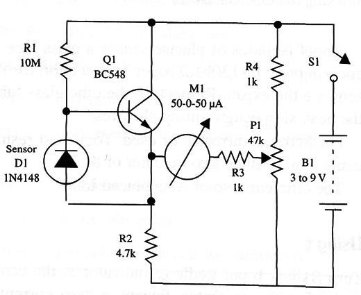
In this project, a reversed-biased silicon diode is wired to the base of a silicon transistor acting as an amplifier. The transistor, & resistor, and a potentiometer form a Wheatstone bridge having a current meter as a zero indicator.
As the equilibrium of the bridge depends on the temperature, the potentiometer can be used to zero it at some reference temperature, and the meter will indicate any change.
Assembly
Figure 2 shows the complete diagram of the thermal biofeedback device.

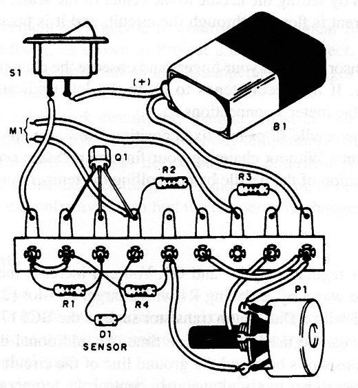
As the circuit is very simple, not critical, and appropriate for a beginner, a terminal strip can be used as the chassis as shown in Fig. 3. In a modern version you can assemble the circuit using a solderless board.

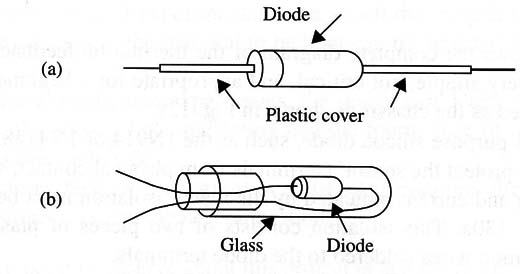
Any general-purpose silicon diode, such as the 1N914 or 1N4l48, can be used as a sensor. To protect the sensor's terminals from physical contact, which can alter the reading and current indicated by the meter, isolation must be provided as shown in Fig. 4.

This isolation consists of two pieces of plastic tubing to cover the common wires soldered to the diode terminals.
Another form of isolation consists of placing the sensor inside a glass tube it in an epoxy block (Fig. 4B). The proper form of protection for the sensor depends on the experiment. Remember that, in the case of the glass tube, the heat flows very slowly through it, resulting in a slow response.
for M1, any microampere current meter can be used. You can get best results usmg A meter with a 50 µA range and zero in the center of the scale.
The circuit is powered from two or four AA cells placed in a holder.
Using the Circuit
Turn S1 on and adjust Pl1to put the needle of the indicator at the center of its scale. For meters with zero in the center, this means a zero current flowing through the circuit. As we can detect only temperature changes, we can use other types of meters by setting the needle to the center of the scale, meaning that some amount of current is flowing through the circuit, and it is possible to detect current changes.
Place the sensor between your fingers and observe the change in position of the meter’s needle. If the needle tends to go to the left (indicating a temperature drop), reverse the meters connections.
Wait until the needle stops in a end position. Now you are ready to start with your experiments. Without changing your fingers’ pressure on the sensor, try to change the position of the needle by controlling the temperature of your body.
Suggestions
Sensitivity is regulated by R1 and Q1. You can increase the sensitivity of the circuit in two ways: by replacing R1 with a larger resistor (22 to 47 M) or by replacing Q1 with a Darlington transistor such as the BC517.
Two sensors can be used at the same time. An additional diode is placed between the transistors base and the ground line of the circuit. This arrangement allows the researcher to simultaneously control the temperature of the fingers of the right and left hand, trying to alter it in a differential mode.
Semiconductors
Q1 - BC548 or equivalent-any general-purpose silicon NPN transistor
D1 - 1N4148, 1N914 or any silicon diode
Resistors
R1 - 10 k, 1/8 W, 5%-brown, black, blue
R2 - 4.7 k, 1/8 W, 5%-yellow, violet, red
R3, R4 - 1 k, 1/8 W, 5%-brown, black, red
Miscellaneous
P1 - 47 k potentiometer
M1 - Microampere meter, 0-50 to 0-200 µA single or With zero in the center of
the scale
S1 - SPST, toggle or slide switch
B1 - 3 to 9 V, AA cells or battery
Terminal strip, cell holder or battery clip, wires, solder, plastic box, etc.


