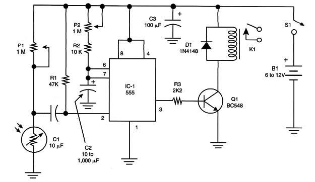
This circuit is a timed version of the circuit described in ART247E.
A simple timed version using the 555 integrated circuit (IC) is shown in Figure 1.

In this circuit, P1 adjusts the sensitivity according to the light source and the ambient illumination. P2 adjusts the time the relay is on after being triggered.
The time on can be calculated by the following formula:
T – 1.1 x R2 x C2
where:
t = the time in seconds (s)
R2 = the adjustment of P2 and R2 in ohm
C2 = the capacitance in farad (F)
The maximum values for R2 and C are 1 M and 1,000 µF.
Timer Version
IC-1 - 555 IC timer
Q1 - BC548 or equivalent general-purpose NPN silicon transistor
D1 - 1N4148 general-purpose silicon diode
P1, P2 - 1 M trimmer potentiometers
R1 - 47 k x 1/8-Watt resistor (yellow, violet, orange)
R2 - 10 k x l/8-Watt resistor (brown, black, orange)
R3 - 2.2 k x 1/8-watt resistor (red, red, red)
C1 - 10 µF x 12-Volt electrolytic capacitor
C2 - 10 to 1,000 µF x 12-volt electrolytic capacitor
C3 - 1,000 µF x 12-Volt electrolytic capacitor
LDR - Any common LDR (see project)
K1 - 6- or 12-Volt relay, 50 mA coil (according to the power supply)
B1 - 6- or 12-Volt cells or power supply (according to the relay)
PCB or solderless board, power supply, wires, solder, etc.


