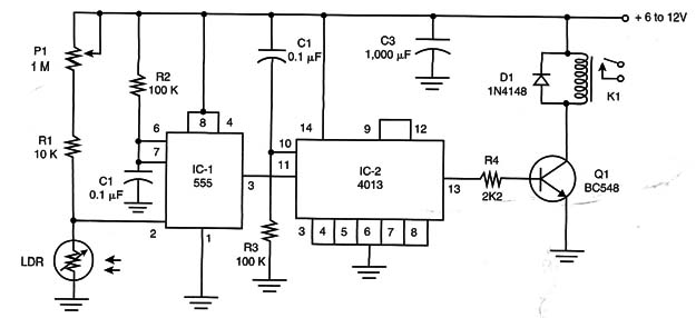
This circuit is a timed version of the circuit described in ART247E.
Figure 1 shows a bistable version based on a configuration explored in previous projects using the D-type complementary metal oxide semiconductor (CMOS) flip-flop 4013.

P1 adjusts the sensitivity and the relay must be rated according to the power supply voltage. Types rated from 5 to 12 volts can be used.
The circuit can be mounted on a PCB or on a solderless breadboard. Take care with the position of polarized components such as the ICs, electrolytic capacitors, transistor, and power supply.
Bistable Version
IC-1 - 555 IC timer
IC-2 - 4013 CMOS D-type flip-flop IC
Q1 -l BD548 general-purpose NPN silicon transistor
D1 - 1N4148. general-purpose silicon diode
K1 - 5- to 12-Volt relay (according to the power supply voltage)
LDR - Any round, common LDR
R1 10 k x 1/8-watt resistor (brown, black, orange)
R2, R3 - 100 k x 1/8-watt resistors (brown, black, yellow)
R4 - 2.2 k x 1/8-Watt resistor (red, red, red)
P1 - 1 M linear or logarithmic potentiometer (sensitivity)
C1,C2 - 0.1 ptF ceramic or polyester capacitors
C3 – 1.000 µF x 12-volt electrolytic capacitor
PCB, wires, solder, power supply, etc.


