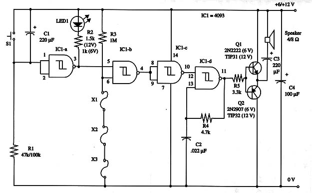
This círcuit wíll power the alarm on after a tíme delay of about 20 seconds. This tíme delay is determíned by R1 and C1.
You can alter the delay period by changíng both R1 and C1.
Values such as C1 = 1,000 µF and R1 = 1,000,000 Ω Will gíve time delays of about 15 min.
Normally closed sensors are used in this alarm, and operation occurs when any sensor ís opened.
You can use Wires or reed swítches as sensors.
Dozens of them can be Wired ín series, and each one wíll cause the alarm to operate.
Currents of only a few milliamperes pass through sensors,wWiring, so they can be placed hundreds of feet away from the circuit without rísk of malfunction.
The circuit drives a loudspeaker with about 1 W of audio tone.
If you use a 6 V power supply, you can use small general purpose transistors such as the 2N2222 and 2N2907 ín the output stage.
However, íf you power the circuit With 12 V supplies, you should use such powerful transístors as the pair formed by TIP31 and TIP32. In thís case, the transistors must be mounted on heatsinks.
The audio tone frequency ís determíned by R4 and C2.
You can vary both Within a large range of values. C2 can range from 0.01 to 0.1 µF, and R4 from 22 k Ω to 1 M Ω.
Better audio reproduction is obtained by enclosíng the loudspeaker in an enclosure.
LED1 ís used to índícate whether the alarm ís on or off.
The LED wíll glow when the alarm ís off.
The current drain ís very low when the alarm is off.
A schematíc díagram of the alarm is shown in Fig. 1.

Transistor selection depends on the power supply voltage.
With a 12 V supply, you have to use transístors TIP31 and TIP32 ín the output stage.
S1 ís a momentary SPST switch and ís used to give the turn-on delay You have to press thís swítch when leavíng your home.
This will give you tíme to pass through the door without setting off the alarm.
IC1 - 4093 CMOS integrated circuit
Q1 - 2N2222 (6 V) or TIP31 (12 V) NPN power transistor (see text)
Q2 - 2N2907 (6 V) or TIP32 (12 V) PN P power transistor (see text)
LED1 - Red common LED
X1, X2, X3 - Normally closed sensors (see text)
S1 - SPST momentary switch
SPKR - 2 or 8 Ω, 4-inch loudspeaker
R1 - 47,000 to 100,000 Ω, 1/4 W, 5% resistor (see text)
R2 - 1,000 Ω (6 V) or 1,500 Ω (12 V), 1/4 W, 5% resistor
R3 - 1,000,000 Ω, 1/4 W, 5% resistor
C1 - 220 µF, 12 WVDC electrolytic capacitor
C2 - 0.022 µF ceramic or metal film capacitor
C3 - 220 µF, 16 WVDC electrolytic capacitor
C4 - 100 µF, 16 WVDC electrolytic capacitor


