The circuit can be used to protect cars and other large objects, the home, and other items, as the sensor can be used to detect any kind of movement. You can also use this circuit to detect movement in scientific experiments.
The relay can drive powerful warning systems such as sirens, horns lamps, and so on.
The circuit can be powered from common cells batteries, and current drain is very low (about 5 mA) when the relay is off.
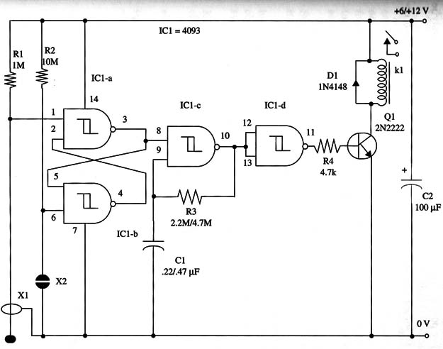
A schematic diagram of the Pendulum Intermittent Alarm is given in Fig. 1.

The relay coil is chosen to match the power supply voltage. You can use a mini DPDT, 1 A relay, Radio Shack 275-249 or, for heavy loads, a 10 A mini SPDT relay, Radio Shack 275-248.
These relays are rate to12 V and drain only 38 mA (coil resistance = 320 Ω).
The turn-on and turn-off frequency is determined by R3 and C1. You can vary the values of these components to alter the intermission rate.
Values can range as shown in the schematic diagram.
Reset is made by a touch switch, but you can also replace this sensor with a common SPST momentary switch.
Proper positioning of the polarized components (diode and electrolytic capacitor) should be observed.
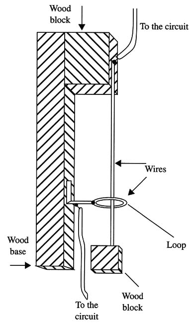
The sensor’s details are shown in Fig. 2.

Note that operation occurs when the vertical bare wire touches the ring due any Vibration.
Pendulum Intermittent Alarm
IC1 - 4093 CMOS integrated circuit
Q1 - 2N2222 NPN general purpose silicon transistor
D1 - 1N4148 general purpose silicon diode
K1 - 6 V or 12 V relay (see text)
X1 - Pendulum sensor (see text)
X2 - Touch sensor or momentary SPST switch
R1 - 1,000,000 Ω, 1/4 W, 5% resistor
R2 - 10,000,000 Ω, 1/4 W, 5% resistor
R3 - 2,200,000 Ω to 4,700,000 Ω, 1/4 W, 5% resistor (see text)
R4 - 4,700,000 Ω, 1/4 W, 5% resistor
C1 - 0.22 µF or 0.47 µF metal film or ceramic capacitor (see text)
C2 - 100 µF, 16 WVDC electrolytic capacitor


