Translated into English by Patricia Lima Carlos.
The LEDs (Light Emitting Diodes) are devices that emit light when traversed by a current, but they operate at very low voltages (typically 1.6 to 2.7 volts) and can burn easily if connected directly to larger voltage sources. The maximum permissible currents they admit are low rarely exceeding 50 mA, except for the jumbo and high brightness types.
Even connecting them to batteries we need to take special care with the use of a limiting resistor in series, otherwise, if the direct connection is made they will burn. There are also cases where we need to use DC/DC converters to increase battery voltage, as in the case of white LEDs that need at least 2.7 V to light up.
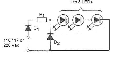
How to connect a LED to a 110 V, 117 V or 220 V, i.e., to the power grid? That's what we'll see. This is really possible, and may have some interesting utilities. One of the applications is as a focus of low-power permanent light for children's bedrooms, thus avoiding the total darkness and indicating the position of the light switch. In Figure 1 we give the circuit which allows the connection of 1, 2 up to 3 LEDs in the network of 110 or 220 V.

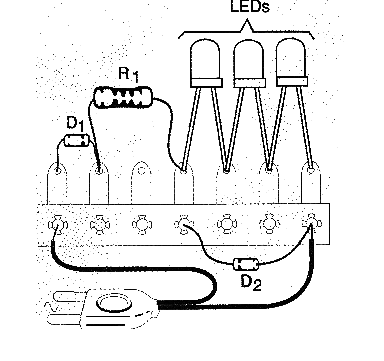
The R1 resistor, which is a 5-watt wire with 10 k ohm for the 110 V or 117 V grid and 22 k ohm for the 220 V one, reduces the voltage and the current to the levels that the LED needs. The diode D1 rectifies the current, because the LEDs only work with continuous currents and D2 protects the LEDs against reverse pulses or problems with D1. In Figure 2 we show how the assembly can be done on a small terminal bridge.

The diodes can be 1N4004, 1N4007 or another depending on the power grid and the LEDs can be of any color or size. During operation the resistor R1 warms slightly, which should be considered normal.
On the 110 V or 117 V grid power consumption is in the order of 1.2 watts and on the 220 V grid in the order of 2.4 W which represents 1 to 2% consumption of an ordinary lamp.
Note: more LEDs can be connected in series in this circuit without any problem of operation. Depending on the LEDs the quantity can reach 20.
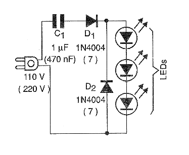
Another interesting and less expensive circuit is the one which makes use of a polyester capacitor to reduce the network voltage, thus taking advantage of its capacitive reactance. This circuit is shown in Figure 3, using a capacitor of 1 µF for the 110 V power grid and 470 nF for the 220 V.

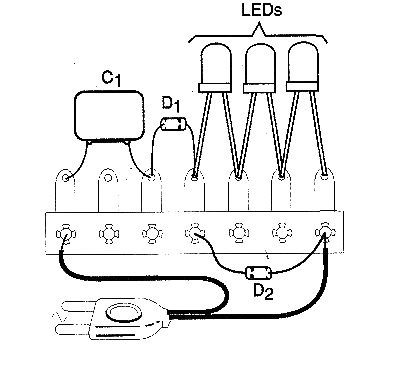
The assembly can also be made in a small terminal bridge and embedded in the wall, as shown in Figure 4.

1 to 5 LEDs of any type connected in series can be supplied. Note that the two circuits are fed directly through the power grid, there is no insulation.
Therefore, no part of it should be exposed as there is a risk of shock in case of accidental contact.
D1, D2 - 1N4004 (7) - silicon rectifier diodes
LED1 to LEDn - Common LEDs of any color
C1 - 1 µF x 200 V (110 V) or 470 nF x 400 V (220 V) polyester capacitor
Miscellaneous:
Terminal strip, wires, weld, etc.


