The circuit is powered from a 12 V car battery, and current drain depends on the lamp and transformer used in the project. Fluorescent lamps ranging from 7 to 40 W can be used.
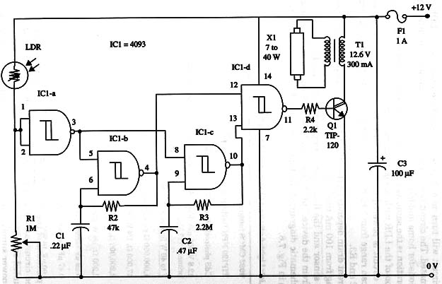
R1 adjusts the turn-on light level. R1 and the LDR are wired as a potential divider, and it is adjusted so that the voltage on IC1-a input is slight less than the gate trigger point. R3 and C2 determine the flash rate and can be altered according the intended application. Cl and R2 determine the frequency of the oscillator formed by IC1-b.
Q1 drives a small transformer that generates high voltage to the fluorescent lamp.
A schematic diagram of the Dark Activated Fluorescent Flasher is given in Fig. 1.

Transistor Q1 must be mounted on a heatsink. The board, transformer, F1, and R1 are housed in a plastic box. The LDR (sensor) should be mounted in a place that receives the ambient light but not the lamp flashes.
The fluorescent lamp can be installed as far as you want from the device, but you must take care with the wiring insulation, because high voltages are present in this part of the circuit.
Change the values of C1 and C2 to get better performance and a flash rate that is appropriate for the application you have in mind.
IC1 - 4093 CMOS integrated circuit
Q1 - TIP120 NPN Darlington power transistor
LDR - CdS photocell
X1 - Fluorescent lamp, 7 to 40 W (see text)
T1 – 12.6 V, 300 mA transformer (see text)
F1 - 1 A fuse and holder
R1 - 1,000,000 ohm potentiometer or trimmer pot
R2 - 47,000 ohm, 1/4 W, 5% resistor
R3 - 2,200,000 ohm, 1/4 W, 5% resistor
C1 - 0.22 µF ceramic or metal film capacitor
C2 - 0.47 µF ceramic or metal film capacitor
C3 - 100 µF, 16 WVDC electrolytic capacitor


