It can be powered by a 9 V battery or AA cells. The low current requirements will extend the life of the cells.
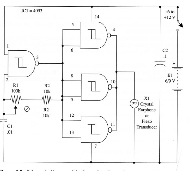
Figure 1 shows the schematic diagram of the insect repellent.

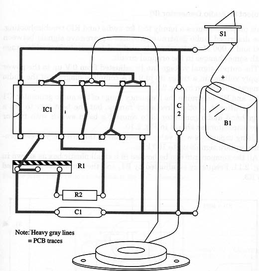
A home-made printed-circuit board is shown in Fig. 2.

All the components and the power supply can be housed in a small plastic box.
Using the insect repellent is very easy. You only have to adjust the trimmer potentiometer R1 to produce a sound with a pitch that is appropriate to the insect you intend to repel.
Experiment until you find the best sound to repel a specific insect. (If in doubt, ask the insect!)
Insect Repellent
IC1 4093 CMOS integrated circuit
X1 - Crystal earphone or piezoelectric transducer, Radio Shack 273-073 or equivalent
R1 - 100,000 ohm, 1/4 W, 5% resistor
R2 -10,000 ohm, 1/4 W, 5% resistor
C1 - 0.01 pF metal film or ceramic capacitor
C2 - 0.1 µF metal film or ceramic capacitor
S1 - SPST switch
B1 - 6 V (four AA cells) or 9 V (battery)


