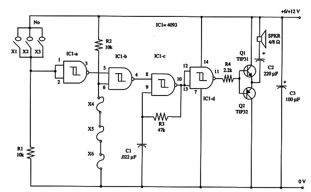
The circuit uses normally open and normally closed sensors, and you can wire dozens of them to protect your home. The device can be powered from battery or ac-to-dc converters.
When the audio is off, the current drain is very low. The drain is determined by R1 and R2, and you can replace these components with 100 kg resistors to reduce the current drain even more.
You can use either a 6 V or 12 V power supply, but you’ll get more audio power with a 12 V supply.
As sensors, you can use wires, micro switches, magnetic switches (reed switches), pendulum sensors, and so on.
You have to connect the sensor according its type at the appropriate input.
Figure 1 is schematic diagram of the Burglar Alarm Center.

Transistors Q1 and Q2 should be mounted on heatsinks. The loudspeaker (SPKR) can be placed in a small enclosure to improve audio reproduction. Proper positioning of the polarized components (electrolytic capacitors and transistors) must be observed.
The parallel sensors are normally open (NO) types such as reed switches, micro switches, and others.
The series sensors are wires normally closed (NC) switches and so forth.
Remember that this is a non-latching system.
You can combine this project with other configurations shown in this book to get a latching alarm.
Reset is accomplished by opening or closing the activated sensor.
IC1 - 4093 CMOS integrated circuit
Q1 - TIP31 NPN power silicon transistor
Q2 - TIP32 PNP power silicon transistor
X1 through X6 - Sensors (see text)
SPKR 4 or 8 ohm, 4-inch loudspeaker
R1, R2 - 10,000 ohm, 1/4 w, 5% resistor
R3 - 47,000 ohm, 1/4 W, 5% resistor
R4 - 2,200 ohm, 1/4 W, 5% resistor
C1 - 0.022 µF ceramic or metal film capacitor
C2 - 220 µF, 16 WVDC electrolytic capacitor
C3 - 100 1uF, 16 WVDC electrolytic capacitor


