What we present is a sound effect circuit consisting of a damped oscillator.
This oscillator produces the sound of a bell, with great perfection, when we turn on the pressure switch.
Its power is made with 4 common batteries or source, and the sound volume depends exclusively on the power of the amplifier used.
There is a single adjustment which is from the point of operation through a potentiometer or trimpot that allows us to find the resonance of the bell, and with that to obtain a more muffled or prolonged sound.
Only one transistor is used and its assembly is very simple.
HOW IT WORKS
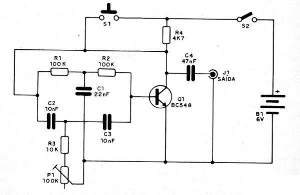
The base of the circuit is a twin-T oscillator in which capacitors C1, C2 and C3 together with resistors R1, R2, R3 and potentiometer P1 determine the sound pitch.
The components must maintain the same ratios of values ??of the circuit, i.e., C1 is twice C2 and C3 and PS with R1 must be adjusted to approximately half of R1 and R2.
The transistor Q1 provides amplification for the signal and thereby enables the oscillations to be maintained.
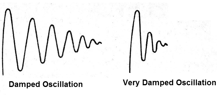
To mimic a bell, the oscillations must be of the damped type, as shown in
Figure 1.

This damping can be faster, resulting in a more muffled or slower sound, resulting in a prolonged sound. The adjustment of this damping is done in the potentiometer Pl. Carefully, by pressing S1 firing the circuit, we can arrive at a perfect imitation of the bell.
Since the transistor provides a low-level signal, we must connect the circuit through J1 to the input of a good amplifier.
ASSEMBLY
In Figure 2 we have the complete diagram of the apparatus, observing its simplicity.

Transistor Q1 can be replaced by any equivalent such as BC237, BC238, BC239, BC547 or BC549. Actually any NPN silicon transistors of general use can be tried.
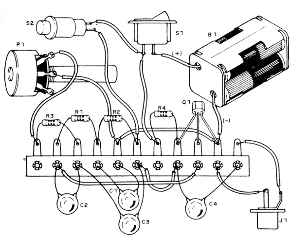
The assembly on a terminal strip is shown in Figure 3.

As a power supply we use 4 small batteries, since the current consumption is very low. If you have a power supply, you can supply power with voltages between 6 and 9 V, without problems.
The used capacitors can be either polyester or ceramic or even paper or oil seized from scrap. The values ??should only be as indicated. The resistors are 1/8 or ¼ W.
A shielded cable must be used for the connection at the amplifier input.
Q1 - BC548 or equivalent
B1 - 6 V - 4 small batteries
S1 - pressure switch
S2 - single switch (optional)
P1 - 100 k - potentiometer or trimpot
R1, R2 - 100k x resistor (brown, black, yellow)
R3 - 10 k - resistor (brown, black, orange)
R4 - 4k7 - resistor (yellow, violet, red)
C1 - 22 nF (.02 or 22kpF) - ceramic or polyester capacitor
C2, C3-10 nF (.01 or 10 kpF) - ceramic or polyester capacitor
C4 - 47nF (.047 or .05) - ceramic or polyester capacitor
Miscellaneous: terminal strip, battery holder, output jack, wires, welding, etc.


