The prospect of finding hidden treasure is undoubtedly what drives most readers to think of building a metal detector.
However, what readers do not know is that detectors, however good they may be, have their limitations, and these often prevent not only easy assembly but also their application in a "treasure hunt."
Common metal detectors are devices which can detect the presence of metals over distances that rarely exceed a few tens of centimeters, depending on the size of the object being considered.
But even though it's not what the reader expects, metal detectors are useful and interesting.
The design which we present in this article is an ultra-simple metal detector, which differs from conventional types by its operating principle.
Its simplicity facilitates assembly and use, but, of course, it also sacrifices other features, such as sensitivity.
Even so, the reader can still use it to find pipes under the wall, small 'hidden or buried objects, or even search people for weapons (Figure 1).

Our detector consists of a "small box" which, when approached with metal objects, changes the tone of the sound of a loudspeaker. This change of tone depends on the size of the metal object and the distance of the device.
As the reader will see, if you make your assembly, there is no secret in the project. Two batteries, one speaker and some common components are required in the assembly.
HOW IT WORKS
Our metal detector is based, like the others, on the changes that metal objects cause in the magnetic field of a coil or a magnet in its vicinity.
A ferrous metal object, as shown in Figure 2, tends to concentrate the magnetic field strength lines of a coil or magnet placed in its vicinity.
In the specific case of a coil, the presence of a metal object in its vicinity causes changes in its inductance, that is, its electric behavior in a circuit.
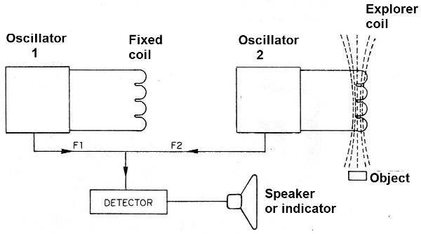
The most elaborate detectors make use of two coils, which are connected to two oscillators, which operate at the same frequency, when far from any external influence.
When the scanning coil approaches a metal object, its influence causes the frequency of one of the oscillators to change. There is then a circuit that "detects" this difference by giving a visual or auditory indication (Figure 2).
Circuits of this type, because they operate at high frequencies (between 100 and 1000 kHz), need adjustments and are of critical assembly, which is not the case with ours.
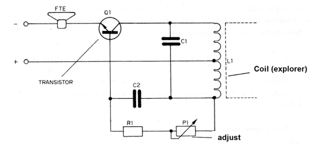
What we do on our ultra-simple detector is to use a single oscillator which produces an audible sound on a speaker at a frequency that can be set from about 1000 Hz to about 5000 Hz. A coil determines the frequency of this oscillator, as shown in Figure 3.
This coil, however, has a different characteristic: it is wrapped in a "U" core, such that its magnetic force lines have to travel through a certain region of the space to close the magnetic circuit (Figure 4).
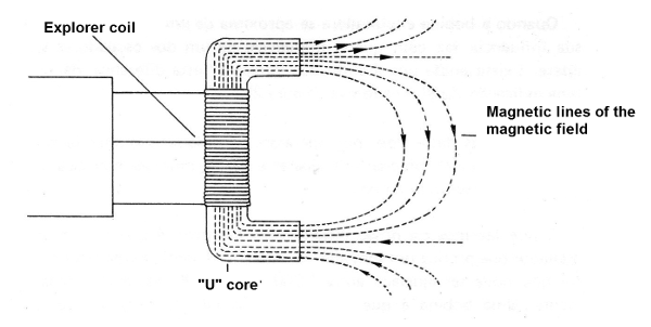
Thus, if any metallic object "enters" the region of the space around the coil, its influence on the magnetic field will cause the oscillator frequency to change.
Depending on the influence, the change will be easily perceived by the operator in the form of a change of tone.
A potentiometer, placed in the oscillator circuit, allows us to obtain the ideal point of operation of the oscillator, so that the small variations of inductance by the influence of metallic objects, are perceived with greater facility.
The range or sensitivity of the appliance depends heavily on the construction and adjustment. At the ideal point, the prototype was able to accuse the presence of common batteries under a board of 2 cm of a table, and objects, of greater dimensions, like a pair of pliers, from a distance of 5 cm.
For the purpose we propose, this sensitivity is perfectly acceptable.
The oscillator circuit is supplied with only two batteries and the current consumption is quite low, ranging from 8 to 30 mA depending on the set point.
MATERIAL
All the material used in the assembly of the detector can be easily achieved.
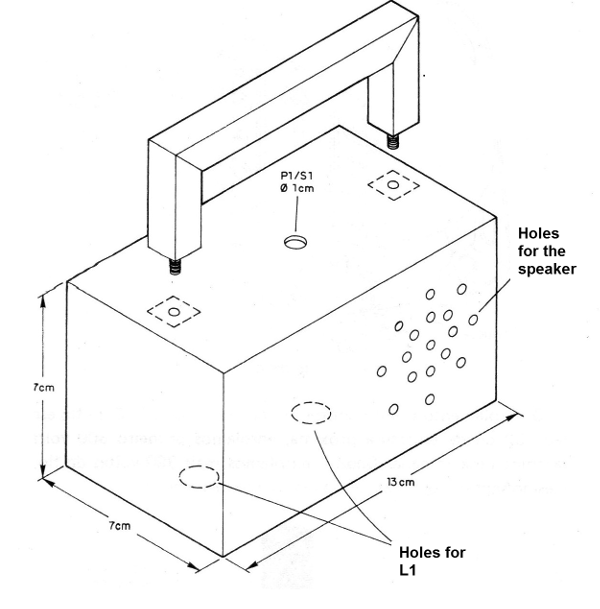
We start with the box, which should have the shape and dimensions shown in Figure 5 to facilitate its use. This box must not have metal in any way, so as not to affect the operation of the detector.
The only component that cannot be bought ready is the explorer coil (L1).
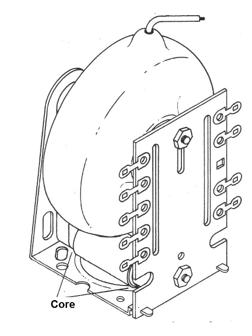
This coil must be wound by the reader himself/herself in a flyback ferrite core. This core can be purchased or taken from an old TV flyback. The flyback is a part, with the format shown in Figure 6, which is usually enclosed in a metal box, next to the high voltage valve of old televisions.
The winding is done as shown in Figure 7.
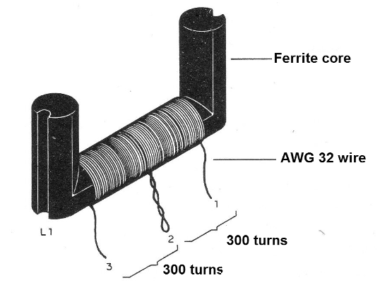
With enameled wire 32 or of close thickness, we first wind 300 turns and make a plug. Then we wound another 300 turns of wire in the same direction, that is, continuing the winding.
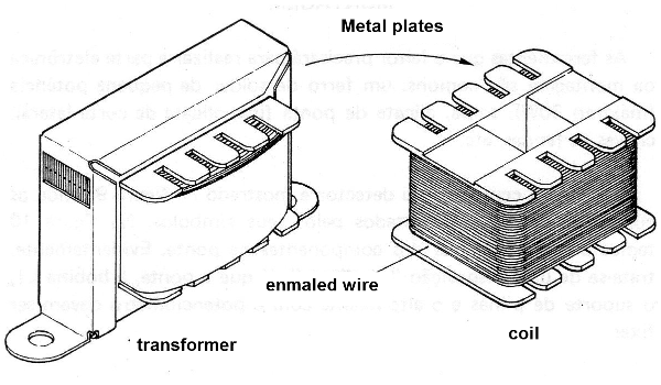
The reader can take advantage of the enameled wire by disassembling some old transformer. If the transformer is only "interrupted or open" your wire will be fine and can be used. It is easy to know if the wire is in good condition, because its color will be bright brown.
If the wire is dark or even black, in the case of a blown transformer, it cannot be used (Figure 8).
To find out if the thickness is in accordance with the design, do the following: wrap 45 turns of wire in a pencil or pen with the side-by-side loops tightly against each other. Then measure the length of the winding. If you get between 0.9 and 1.1 cm you can use the wire because its thickness is close to 0.2019 mm which corresponds to the number 32 AWG.
Finishing the winding of the coil on the ferrite rod, secure the ends of the wires with insulation tape and scrape their ends so that welding can adhere.
The rest of the components do not present any problem.
The capacitors can be all ceramic type disk, and the only resistor is 1/8 W. The potentiometer incorporates the switch that turns the detector on and off, but nothing prevents it from being separated.
The speaker is 8 ohms, 5 cm in diameter, of the type found on portable radios.
The reader will also need a support for two small batteries, as well as a terminal bar, which will serve as a chassis.
Wires, welding, bolts with nuts, plastic knob for potentiometer, complement the material list.
ASSEMBLY
The tools which the reader will need to perform the electronic part of the assembly are common: a small-power welding iron (maximum 30 W), welding, thin-nose pliers, side cutters, screwdrivers, etc.
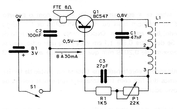
The complete circuit of the detector is shown in Figure 9, where the components are represented by their symbols.
In Figure 10, we have the actual arrangement of the components on the strip.
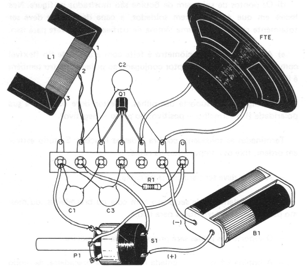
Of course, this is a "scattered" arrangement, since the strip, the L1 coil, the battery holder and the speaker with the potentiometer must be fixed in the box.
In order to avoid any problems with the assembly, the reader should beware of the following:
a) When welding the transistor, observe its position. The flat part should face up. Do the welding operation quickly, so that the heat does not reach the body of the transistor, which can cause damage.
b) The welding operation of the capacitors and the resistor must also be done quickly, so that the heat does not damage them. Capacitor values ??can come in several ways. Like this:
C1: 0.047 - 47n - 47k - 473
C2 = 100-0.1-10-104
C3: 27 (followed by any capital letter)
c) The connection of the speaker can be made with two pieces of plastic flexible wire, approximately 15 cm (giving space for its attachment to the box).
d) The welding points of the coil are shown in the figure. Where the wires are welded, the enamel cover should be thoroughly scraped. Use a razor blade or a pocket knife for this.
e) The connection of the potentiometer is made with the help of flexible wire with plastic cover. The switch connected to the potentiometer is also connected in the same way.
f) When connecting the battery holder, the polarity must be observed (red - positive wire, black - negative wire).
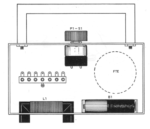
After welding, check all the connections. If everything is in order, fix the components in the box.
The strip must be screwed into the box.
The speaker can be stuck with glue or clamps, or even screws if there are holes for it.
The battery holder will be secured by a clamp.
The coil L1 can be glued or clamped so that the ends of the "U" are outward (Figure 11).

To use this detector see the following item.
TEST AND USE
With the device ready, we can test the operation.
To do this, turn it on by pressing the switch on P1. The loudspeaker should immediately emit a whistle. Turning the potentiometer, the whistle should change its pitch.
If no whistle is issued, the reader should first check the welding points of the coil on the terminal bridge. If they are scraped incorrectly, there will be no contact, damaging the oscillation.
See also the position of the batteries in the holder and if they are in perfect contact with it.
Once the oscillation is obtained, look for the adjustment point where you notice a transition of the sound, from the high to the low pitch, with a minimum of potentiometer movement. There is a point where this transition, which continues throughout the range, is suddenly made by a "leap."
Leaving it on the high pitch, close to the “leap”, we have the highest sensitivity.
By bringing a metal object closer to the device, there must be a clear shade change.
To use the device, simply go through the place where you want to locate the object, being aware of changes in tone. (Figure 12)
On the knob of the potentiometer mark the ideal set point.
Q1 - BC547 or equivalent (BC548, BC237 or BC238) - transistor
L1 - explorer coil (see text)
FTE - Speaker 8 ohm x 5 cm.
P1 - 22 k - pot potentiometer with key
R1 - 1k5 x 1/8 W - resistor (brown, green, red)
C1 - 47 nF - ceramic capacitor
C2 - 100 nF - ceramic capacitor
C3 - 27 pF - ceramic capacitor
B1 - 3 V battery - two small batteries
Miscellaneous: terminal bridge, assembly box, wires, welding, knob for the potentiometer, ferrite core for the coil, enameled wire 32, etc.


