The experiments available to the reader using this device are basically the same as described in other projects in this site. The difference is that the output is used to stimulate the skin of a subject. Some suggested experiments are described below. The circuit is powered from common cells.
Experiments
Obs. This circuit was originally indicated to perform experiments in paranormal electronics and published in my book Electronic Projects from the Next Dimension but canal so be used in biology experiments.
- The presence of. an electrical stimulus in the subject, based on changes in his own skin resistance, can be studied in ESP experiments. The reader can study how this “external” input alters (increases or decreases) the paranormal abilities of an individual.
- Sensitive objects or living beings can be placed between electrodes, and the subject will be auto-stimulated by the voltage produced by the circuit. Experiments to control this voltage using mental powers can be made using this circuit. The circuit can be used to produce current fields in flower pots or biological conductions produced by their own stimulus.
- The circuit can be used to help the subject to reach the fourth state of consciousness or to go into a trance state. The aim of the experiment is to keep the output voltage and frequency constant without altering the pressure of the hands or fingers on the electrodes. Many experiments in transcendental meditation and biofeedback can be conducted based on this configuration.
- Place sensitive objects on the electrodes and try to alter the output voltage by focusing your mental powers on the subject. Experiments in telekinesis can be made by adding a few variations to this basic configuration.
- In all the experiments suggested above, the influence of a pendulum can be explored when working with radiesthesia.
- The output of the circuit can be applied to the leaf of a plant. The electrodes will be placed on other leaf. The experimenter can study how the plant itself might control the voltage of the circuit.
- Plugging the circuit into a fluorescent lamp, experiments with modulated light are possible.
How It Works
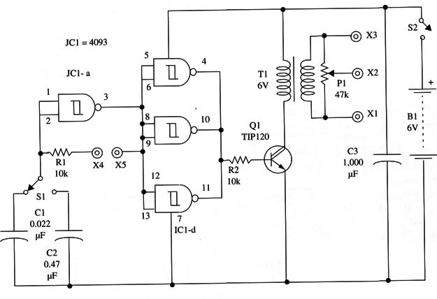
A gate of a 4093 IC is used as an oscillator where the frequency is determined by C1 or C2, R1, and the resistance between the terminals X4 and X5, where the electrodes are placed. As the resistance between X4 and X5 changes, the frequency also changes.
The square signal produced by this block is applied to the input of three other NAN D gates that exist in the 4093 and are wired as buffer-inverters. The signal at the output of this digital amplifier is then applied to a power NPN Darlington transistor.
The load of this transistor is the low-voltage winding of a transformer. The pulses applied to this winding appear as high-voltage pulses in the other winding and are applied to terminals C 1, X2, and X3 where electrodes are connected. One of the electrodes is placed in X2, where the potentiometer P1 can be used to control the intensity of the stimulus.
The circuit is powered from AA cells but, using common power supply transformers, high-voltage pulses up to 300 V can be produced. Of course, these pulses are not dangerous, as they are short and limited in current.
Otherwise, the pulses are strong enough to drive a fluorescent lamp that will flash according the resistance between electrodes. Many experiments can be performed using this circuit.
Assembly
Figure 1 shows the diagram of the high-voltage generator used for electroshock.

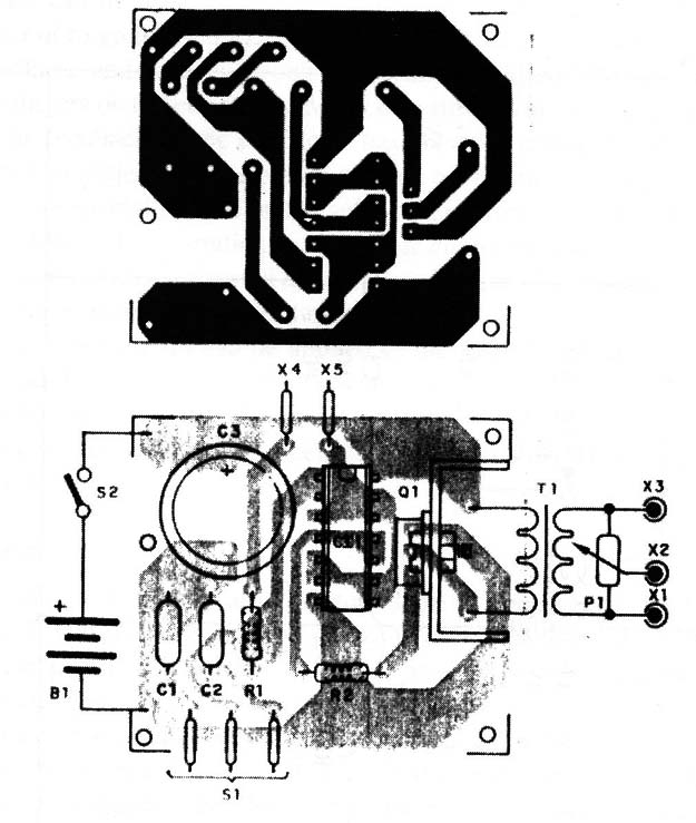
The components can be placed on a small printed circuit board as shown by Fig. 2.

For Q1, you can use any medium-power Darlington transistor with collector current rated to 1 A or more. This transistor must be installed on a small heatsink.
Any transformer with a secondary rated to voltages between 5 and 12 V and currents in the range between 50 mA and 300 mA can be used. The primary can be rated for 117 Vac or 220/240 Vac.
The type of electrodes required depends on the experiment.
As a sensor, you can use small metal plates upon which the fingers are placed or metal rods. For the stimulation electrodes, you can use small metal plates fixed to the skin by rubber bands or even rods to be grasped in the subject’s hands.
In some cases, you need to add a 2.2 M ohm resistor between X4 and X5 to keep the circuit from going into a non-oscillating condition. This condition can increase the current produced by Q1, producing excess heat and draining the cells.
The circuit can be placed in a small plastic or wooden box and to the connection of the electrodes bornes or banana jacks can be used.
Testing and Using the Circuit
Insert a 100 k ohm to 1 M ohm resistor between X4 and X5 and connect a pair of metal plates as electrodes between X1 and X2. Set the potentiometer P1 to its minimum output. S1 must be placed in a position to connect C1 to the circuit. Turn on the circuit and place your fingers on the electrodes.
Open P1 slowly until you feel the signal produced by the circuit, first as a slight sensation of itch. Continue until the sensation becomes a light shock. (Don’t continue to the point where it becomes painful.) Now, move S1 to the position in which C2 is connected to the circuit and experiment it again.
The next step is to replace the resistor between X4 and X5 with a sensor and perform the experiments.
When in operation, let the subject adjust Pl by himself. Don’t forget to adjust it to the minimum value before starting with the probes!
Suggestions
Place an LDR between X4 and X5 to make experiments with light (see the next project, “Third Eye”).
A fluorescent lamp can be connected between X3 and X4 to perform experiments with a visual feedback.
C2 can be increased to values as high as 4.7 µF to allow the circuit to produce widely spaced pulses. In this case, add a 47 Q resistor in series with the transistor emitter to avoid draining excess current from the cells.
Transistor Q1 can be replaced by any power FET without making changes in the original circuit.
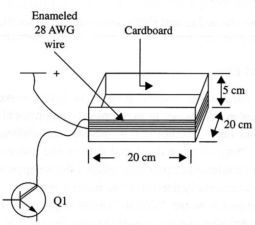
Replace T1 with a coil formed by 20 to 100 turns of AWG 28 wire in a cardboard form as shown in Fig. 3.

The circuit can be used to apply magnetic fields to subjects as controlled by the resistance between X4 and X5.
The fluorescent lamp placed between X1 and X3 can be of the “black light” type, such as the ones used in night clubs. Experiments with UV can be performed this way.
Semiconductors
IC1 - 4093 CMOS integrated circuit
Q1 - TIP120, medium-power silicon N PN transistor
Resistors
R1, R2 -10 k ohm, 1/8 W, 5%-brown, black, orange
Capacitors
C1 - 0.022 11F, ceramic or metal film
C2 - 0.47 11F, ceramic or metal film
C3 -1,000 µF/ 12 WVDC, electrolytic
Miscellaneous
P1 - 47 k ohm - potentiometer
T1 - Transformer: primary 117 Vac, secondary 6 V, CT, 250 to 500 mA
S1 - SPST, toggle or slide switch
S2 - One pole, two positions switch
B1 - 6 V-four AA or C cells
X1, X2, X3 - Output electrodes (see text)
X4, X5 - Input electrodes (see text)


