The circuit is simple, using three transistors, and its power can be made with two or four small cells. With this power the sound is already quite good in terms of volume, but as always, there is the option of using the external amplifier.
The reader will be able to mount this unit on a printed circuit board or a terminal bridge, depending on its availability.
OPERATION
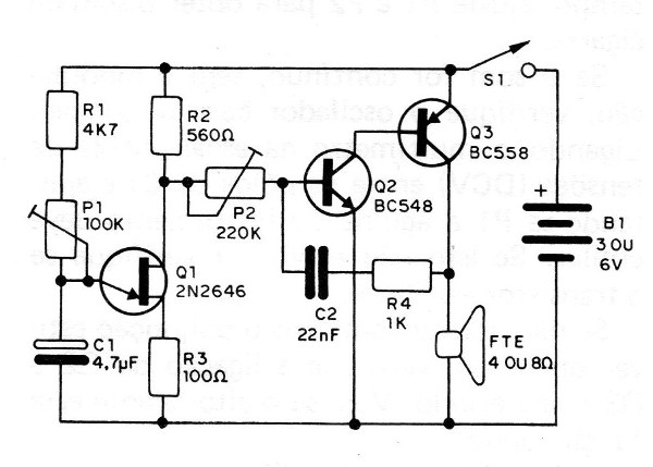
What we have, actually, are two oscillators in this device. The first is a relaxation oscillator with unijunction transistor, type 2N2646, which modulates the corner of the cicada, that is, makes it shivering.
The frequency of this oscillator is set at P1 and also depends on the capacitor C1.
The second oscillator uses two complementary transistors, one PNP and another NPN. Feedback is given by C2 and R4. This capacitor C2 together with the setting in P2 is that determines the timbre of the corner of the cicada.
The reader can further reduce capacitor 02 if you want a sharper corner.
The sound output is output from an 8-ohm speaker, which may be 5 or 10 cm in diameter. The power is supplied with a voltage of 3 or 6 V and the current consumption is relatively low, which guarantees good battery life.
ASSEMBLY
The complete circuit of the cricket is shown in figure 1.

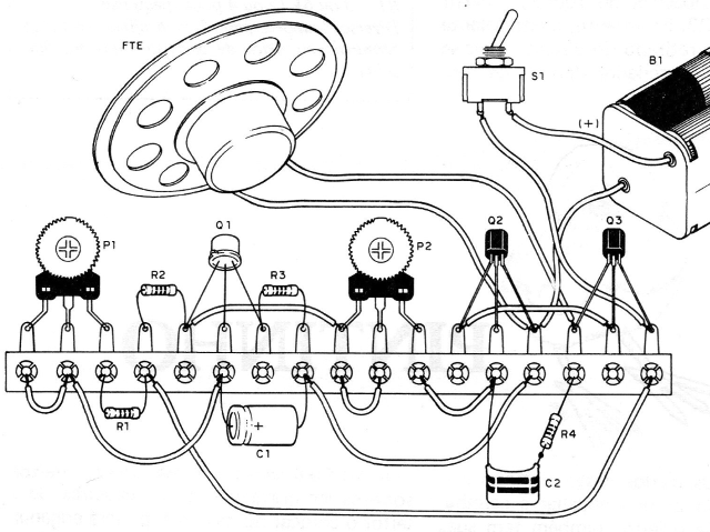
In figure 2 we have the simple assembly in bridge of terminals.

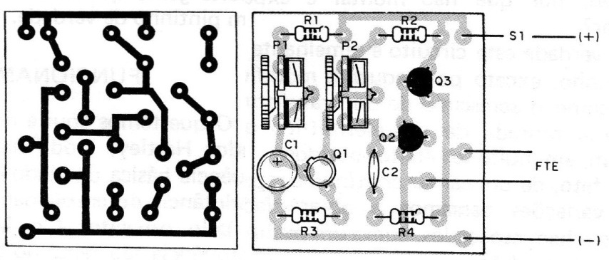
In figure 3 the printed circuit board assembly.

The main precautions that must be taken during assembly are:
a) Observe the position of the flap of transistor Q1 when placing it, because if there is inversion, the unit will not work. Be quick when welding this component.
b) Be careful not to confuse Q2 and Q3, which are different. Their positions also need to be carefully observed, otherwise the cicada will not sing.
c) When soldering capacitor C1, the reader must observe its polarity, which is marked in its enclosure.
d) When placing the other capacitor (C2), the reader only needs to be careful that excess heat does not damage it.
e) The resistors have their values ??given by the colored bands according to the material list. Be careful not to change them.
f) To solder the trimpots, the reader must eventually open its terminals (bridge) or widen the holes (plate). Beware of the values ??of these components.
g) If your assembly is bridged, make the interconnections using short pieces of common wire.
h) Complete the assembly with the speaker connection, battery holder and main switch S1. For the battery holder, obey the polarity. The red wire corresponds to the positive pole.
After that, just test the device.
TEST AND USE
Check the assembly and, if everything is in order, place the batteries in the holder.
Turn on the main switch and at the same time set P1 and P2 to get the buzzer sound.
If the sound is continuous, without modulation, check the oscillator with the unijunction.
By connecting the multimeter on the low voltage scale (DCV) between the C1 poles and adjusting P1 the instrument needle should oscillate. If this does not happen make sure the transistor is OK.
If there is no sound but the unijunction is operating, check the connection of Q2 and Q3 and their status. Make sure the speaker is working.
The connection to an amplifier can be done via a capacitor of 100 nF, from the collector of Q3. However, the speaker cannot be removed from the circuit, otherwise the oscillator will stop working.
Q1 - 2N2646 - unijunction transistor
Q2 - BC548 or equivalent - NPN transistor
Q3 - BC558 or equivalent - PNP transistor
FTE - 4 or 8 ohm speaker
P1 - 100 k - trimpot
P2 - 220 k - trimpot
C1 - 4.7 uF x 6 V - electrolytic capacitor
C2 - 22 nF - ceramic or polyester capacitor
R1 - 4k7 x 1/8 W - resistor (yellow, violet, red)
R2 - 560 R x 1/8 W - resistor (green, blue, brown)
R3 - 100 R x 1/8 W - resistor (brown, black, brown)
R4 - 1k x 1/8 W - resistor (brown, black, red)
S1 - single switch
B1 - 3 or 6 V (2 or 4 small batteries)
Miscellaneous: support for 2 or 4 batteries, terminal strip or printed circuit board, wires, solder, etc.


