In fact this circuit is similar to the bird (ART438E), except for small modifications like the addition of a transformer and the withdrawal of an electrolytic that alter, to a great extent, the effects obtained.
In fact, from a continuous and rapid chanting with variations we get short, well spaced jokes, like a chick that is lost. The player can use this device for a variety of purposes, from sound effects to recordings to banter. If you put it in a box, you can fool a lot of people into believing that there is a real chick in it.
OPERATION
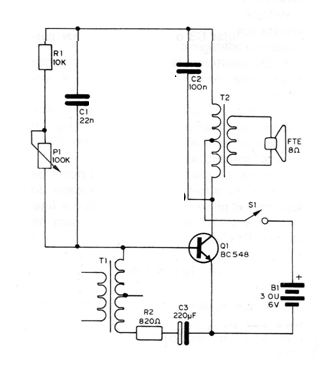
What we have here is again a modified Hartley oscillator, where the basic frequency of the tune is determined by the inductance of the primary winding of T2 and the capacitor C2. Modifications to this frequency are made in trimpot P1 to obtain the exact timbre of the chick.
The gap of the jokes and their duration are determined by an RLC circuit formed by T1, R2 and C3. In T1 what is used is only a winding, the primary, in determining the time of each chirp.
Circuit power can be supplied with 3 or 6 V voltages, but if the reader really wants too much noise, a larger external amplifier can be used. S1 switches the circuit on and off, but can be omitted because the power consumption is low and the unit can be switched off by removing the batteries from the stand.
ASSEMBLY
The complete chick circuit is shown in figure 1.

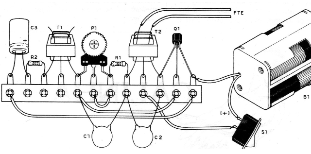
In figure 2 we have the bridging of terminals.

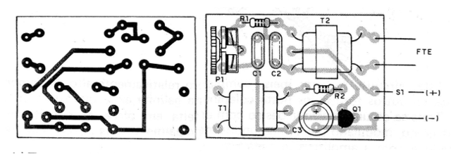
Figure 3 shows the printed circuit board version.

To succeed with your chick, the reader should follow the following recommendations:
a) Observe the position of transistor Q1 when doing your welding. See to what side your flattened side is facing and be quick in welding.
b) Be careful with the transformers so as not to reverse them. Be quick in welding because your terminals are delicate. It will be convenient to have these transformers in hand before making the board, as they vary in size depending on the manufacturer.
c) When soldering CB the reader must be careful with its polarity.
d) For other capacitors, the reader only needs to observe their values ??and be fast in the welding.
e) The resistors have their values ??given by the colored bands. See the material list.
f) The trimpot needs larger socket holes in the plate to freely enter or be slightly adjusted at its terminals to be welded to the bridge.
g) Connect the S1, the battery holder and the speaker. The polarity of the battery holder must be followed and the speaker connection can be made with flexible common wire.
PROOF AND USE
Insert the batteries into the battery holder. Turn on main switch S1 (if used).
Set P1. The device must emit, in a certain setting position, chick-like jokes. Find the position that gives the sound more like the chick.
If you have difficulty adjusting, the reader can try changing the capacitors C1 and C2, changing their values at will until you get the desired tone.
Depending on the type of transformer, this compensation must be made to achieve optimal sound.
The C3 capacitor can also be modified according to the duration and range of the jokes.
Q1 - BC548 or equivalent - NPN transistor
TI, T2 - output transistors for transistors, with primary from 500 ohm to 1 k and secondary from 8 ohm
P1 - 100 k - trimpot
R1 - 10k x 1/8 W - resistor (brown, black, orange)
R2 - 820 R x 1/8 W - resistor (gray, red, brown)
C1 - 22 nF - ceramic capacitor
C2 - 100 nF - ceramic or polyester capacitor
C3 - 220 uF x 6V - electrolytic capacitor
S1 - single switch
FTE - 8-ohm speaker
B1 - 3 or 6 V (2 or 4 small batteries)
Miscellaneous: support for 2 or 4 batteries, terminal strip or printed circuit board, wires, solder, etc.


