One way to know if a remote load is receiving power is to monitor the current in its circuit. However, depending on the intensity of this current the interruption of the circuit can be problematic. And if the operating voltage of the circuit is high there is still the danger of having an indicator under high potential which is not always convenient.
If these problems were not enough, we still have the fact that the introduction of an indicator circuit to monitor a distant load can mean a voltage drop with eventual loss of efficiency.
How to monitor a remote circuit without these problems?
Practical Idea
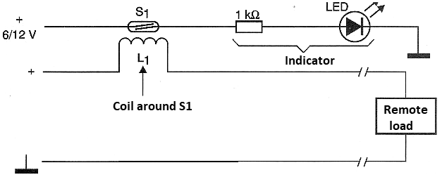
As shown in Figure 1, for a direct current circuit, it is sufficient to use the feed field itself when it passes through a low resistance coil which does not therefore cause losses in the circuit.

This field is used to trigger a reed switch that then triggers the remote indicating circuit. Two advantages should be emphasized in this circuit: the first is that it is totally isolated from the monitored circuit and the second is that the low impedance of the coil does not cause appreciable losses in the fed circuit even if it is of low voltage.
We can also indicate the possibility of the indicator circuit operating with a completely different voltage from the monitored circuit.
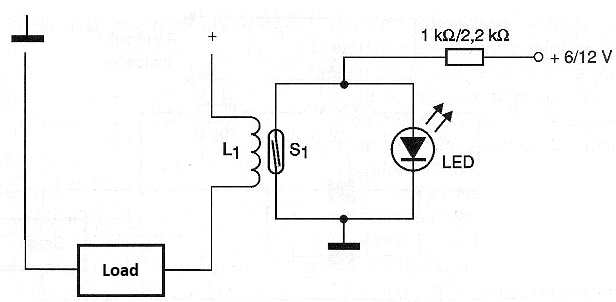
In figure 2 we have a variation of this circuit that operates "in reverse", that is, an indicator LED stays off when the current is circulating through the load.

The number of turns of the coil that will be wrapped around the blade switch depends on the intensity of the current to be monitored and the sensitivity of the switch. Normally, for a current of 1 A it is enough a few turns to obtain the closing. The thickness of the wire used must be compatible with the current intensity to be monitored.
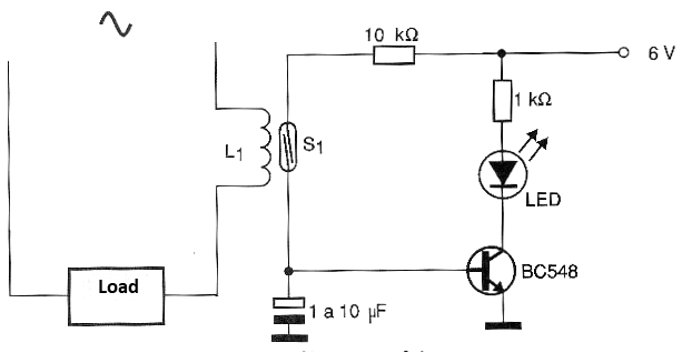
For alternating currents in which the switch blades tend to vibrate we have the circuit shown in figure 3.

This circuit controls a transistor through a capacitor so that with the pulses generated by opening and closing the switch (at the frequency of the monitored current) the capacitor remains charged and thus the transistor in conduction.
The signal to the monitor (which can be an indicator) is therefore a continuous voltage. In this case also, the number of turns around the switch depends on the current intensity and its sensitivity.
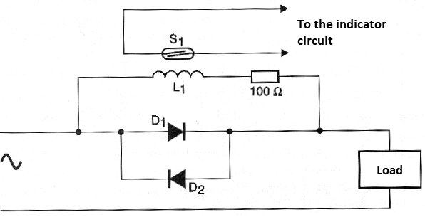
Finally we have in Figure 4 a circuit for higher currents in which the coil around the reed switch can be coiled with very thin wire and thus be formed by 100 to 500 turns with the production of fields with very low currents.

In this circuit the main current passes through the diodes, obtaining a two-way 0.6 V. The current in the coil of the indicator circuit will be determined by its resistance added to that of the resistor. The applied voltage will be only 0.6 V in this circuit.
CONCLUSION
Variations around these circuits can be elaborated at will by imaginative readers. The use of reed relays such as the ones offered offers a wide range of options for current-driven circuits with full insulation which can be very important in industrial applications.


