This stimulus or "reactivation," which simply extends the useful life of an ordinary battery, can be done by passing a current in the opposite direction to the normal, that is to say, that which occurs when it supplies energy.
Whether the reader will use many batteries in their experiments or still want to show how batteries can be reactivated the assembly of this design may be interesting. The simple apparatus we describe allows the reactivation of small, medium or large common batteries and will prolong their life. It basically consists of a power supply with current limiting.
HOW IT WORKS
The current that must circulate through the cells for reactivation must be continuous and there must be some type of device that limits its intensity. If the current is too intense, excessive heat may be generated inside the battery and even gas bubbles that will cause the battery to leak or, worse, explode.
Thus, in our charger we have at the input a transformer that lowers the voltage of the power network to a safe value and at the same time isolates the network so that there is no danger of shocks in its handling.
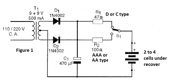
The alternating voltage obtained in the transformer is then rectified by diodes and then filtered applied to a resistor in series with the batteries that must be reactivated. The resistor is the current limiter that prevents high currents from flowing, thus causing heating problems or even danger of explosion.
ASSEMBLY
In figure 1 we have the complete diagram of the apparatus.

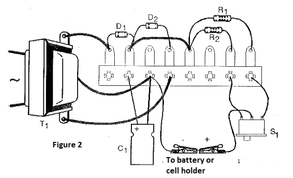
In figure 2 we have the arrangement of its components in a terminal strip.

The transformer has primary winding according to the power network (110 V or 220 V) and secondary winding of 9 + 9 V with current from 300 to 500 mA.
The diodes are of type 1N4002 or equivalent and the electrolytic capacitor must have a working voltage of 16 V or more. The resistors R1 and R2 that determine the intensity of the reactivation current according to the batteries are 1 watt or larger. The switch S1 switches the resistor, thus determining the intensity of the reactivation current of the batteries according to their type.
For batteries we suggest the use of brackets according to their size. Note that the connection of the stand must be made with care to the polarity of the wires.
TEST AND USE
Simply put the batteries to be re-activated in the holder and turn the unit on. Also check that rechargeable batteries are no longer in an overdrive state when there are signs of leakage or corrosion. In this case, do not attempt to reactivate since there is no possibility of having a good result, they can still leak, putting the integrity of the device at risk. Do not attempt to reactivate any type of battery other than ordinary batteries, as there is a risk of leakage or explosion.
The reactivation time of ordinary dry batteries can vary from 30 minutes to 2 hours. If after this time any of the batteries do not "show signs of recovery", do not try again, because there is no longer any substance that can be reactivated inside. Throw the pile away.
When connecting the battery holder always observe the polarity by the color of the claws.
WHAT TO EXPLAIN
Explain the principle of common batteries and why they can’t be recharged: the reaction that produces energy is irreversible. Show how an electric current flowing through the battery can reactivate.
Explain in rechargeable batteries and batteries the principle of operation is different and the reverse current actually reverses the chemical reaction by recharging them.
SUGGESTIONS
If you have skill, see how to make a lead-acid accumulator. This battery can be recharged many times by our device. See, however, that in this accumulator enter toxic substances that require very careful handling. Ask the science teacher for guidance. This unit can also recharge nicad batteries. Take the time to explain how they work.
This power supply can also be used in experiments involving current fields or other applications requiring continuous currents.
D1, D2 - 1N4002 or equivalent - silicon diodes
T1 - Transformer with primary according to the local and secondary network of 9 + 9 V x 300 mA
C1 - 470 uF /16 V - electrolytic capacitor
R1 – 47 ohm x 1 W - resistor - yellow, violet, black
R2 - 100 ohm x 1 W - resistor - brown, black, brown
S1 - 1-pole x 2 positions
Several:
Mounting box, power cable, terminal bridge, battery holder, alligator clips, wires, solder, etc.


