We describe a sensitive sonic relay or Vox that can be used for a wide range of purposes. The circuit uses a ceramic, piezoelectric or crystal microphone with a good sensitivity, set in a trimpot or potentiometer.
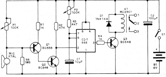
Power is supplied by batteries or power supply and the controlled load depends only on the relay used. The operation of the circuit is simple to understand. Q1 and Q2 form a signal amplifying stage where the gain is set at P1.
In the original circuit no resistor was provided to limit the current in this circuit, but it can be added in series with the potentiometer. A 10 k ohm resistor will be enough to guarantee this protection. The signal from the amplifier is to trigger a 555 in the monostable configuration where the drive time depends on C1 and the P1 setting.
For longer times, C1 and P2 may have higher values, up to 1 500 uF and 2.2 M ohms when the time will reach 1 hour. To activate the relay we have a final transistor connected to the output of the 555.
Assembly
In figure 1 we have the complete diagram of the control.

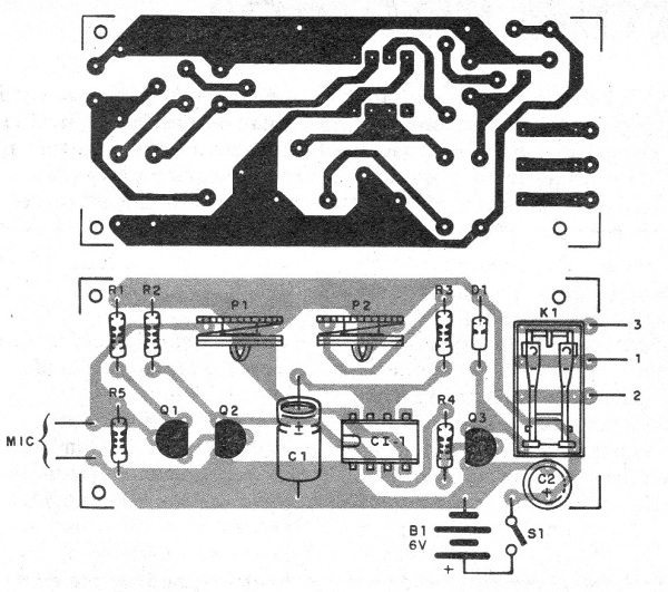
The printed circuit board for the assembly is shown in figure 2.

On assembly, observe the positions of the integrated circuit and transistors. The board is for DIL-based relays, but other types with tripping current up to 100 mA can be used by modifying the board. The resistors are 1/8 W with any tolerance and the electrolytes for 12 V or more working voltage.
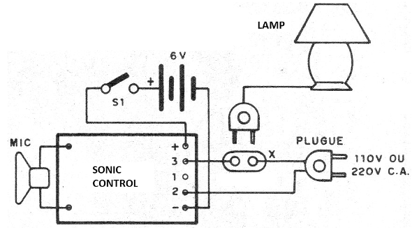
The microphone must be of high impedance and if source is used, it must provide at least 250 mA. The cable to the microphone should be shielded, especially if it is longer than 20 cm. In figure 3 we have the way to connect an external load to drive by the circuit.

Other devices can be controlled such as recorders and sound systems.
CI-1 - 555 - integrated circuit
Q1 - BC558 - PNP general purpose transistor
Q2, Q3 - BC548 - general purpose NPN transistors
D1 - 1N4148 - general purpose diode
K1 - Sensitive 6 V Relay
S1 – On/Off switch
B1 - 6 V - 4 batteries or power supply
P1, P2 - 100 k ohm - trimpots or potentiometers
C1 - 10 uF - electrolytic capacitor - see text
C2 - 100 uF - electrolytic capacitor
R1, R4 - 1k ohm - resistors - brown, black, red
R2 - 47 k ohm - resistor - yellow, violet, orange
R3 - 4k7 ohm - resistor - yellow, violet, red
R5 - 1M5 ohm - resistor - brown, green, green
Several:
Printed circuit board, battery holder, mounting box, wires, solder, etc.


