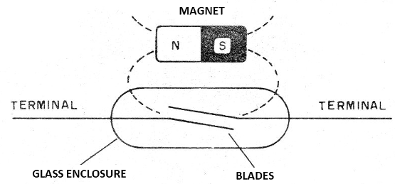
Reed switches, or blade switches, consist of components that can be used to turn a circuit on or off by the action of the magnetic field of a magnet, as shown in Figure 1.

However, these switches have little control capability, typically a few hundred milliamps, which limits their application. Auxiliary circuits must be used to control larger loads. However, the reed-switch is not the only option we have to connect a circuit from the magnetic field of a magnet.
An interesting option is to use a pickup coil attached to an SCR and this is what we will do in this project. Approaching a rapidly moving magnet near a pickup coil induces a pulse of sufficient intensity to trigger an SCR and thereby control a relay.
In our case, as the circuit is powered by DC voltage, once tripped the circuit remains in conduction. To turn it off, the power must be interrupted for a moment.
Assembly
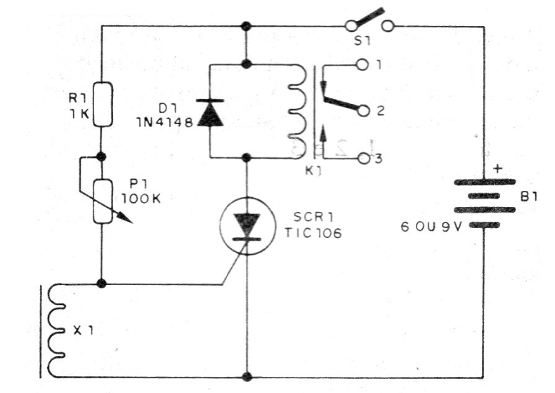
In figure 2 we have the complete diagram of the apparatus.

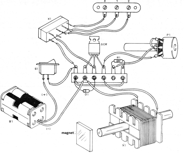
Since this is a very simple assembly, we chose the terminal strip version of the terminals, shown in figure 3.

The SCR can have any suffix, and does not need a heatsink. Observe its position and the polarity of the diode. The coil is the primary winding of any small transformer from which the core has been withdrawn and a ferrite rod inserted. For power supply, it may be necessary to use 9 V to compensate for the 2 V voltage drop in the SCR.
To trigger, simply lean on the stick or pass a permanent magnet close to it.
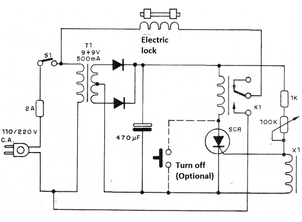
In figure 4 we have a suggestion of a complete circuit of an electronic lock with the rearmament system.

The rectifier diodes are 1N4002 or equivalent and the trimpot is used to adjust the sensitivity. To test, just go near the magnet of the sensor and adjust the trimpot or potentiometer at the same time.
SCR -TIC106 - see text
D1 - 1N4148 - general purpose diode
P1 - 100k ohm at 1M ohm - trimpot or potentiometer
K1 - 6 V Sensitive Relay
S1 – On/Off switch
B1 - 6 V - 4 batteries or power supply
X1 - Sensor - see text
R1 - 1k ohm x 1/8 W- resistor - brown, black, red
Several:
Terminal strip, battery holder, wires, solder, etc.


