The circuit presented has a power of a few watts, and can excite a piezoelectric tweeter that has good performance up to about 25 kHz. With this, we can reach the inaudible range for humans, but within the auditory range of many animals.
The circuit uses common components and has a frequency setting. The transistor can be replaced by a power MOSFET and power supplied with 12 V to further increase the output power.
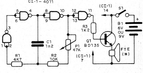
Basically the circuit consists of an oscillator drawn around three of the four 4011 NAND gates. The fourth port is used as a digital amplifier that excites the output transistor. The frequency depends on C1 and the setting of P1.
Assembly
In figure 1 we have the complete diagram of the emitter.

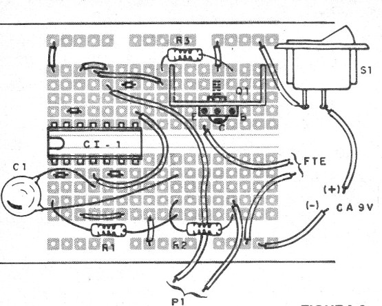
The assembly can be done in a protoboard matrix if the purpose of the project is experimental or didactic, as shown in figure 2.

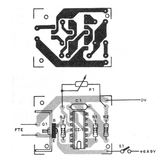
For a definitive version, we have the printed circuit board shown in figure 3.

On assembly, note the position of the integrated circuit and transistor. The resistors are 1/8 W with any tolerance and the capacitor can be ceramic or polyester. For power supply use medium or large batteries, given the consumption, being the ideal use of a source of at least 300 mA.
To adjust, turn on the unit and turn P1 until the sound becomes very sharp and then disappear.
CI-1 - 4011 - integrated circuit
Q1 - BD135 or equivalent - medium power NPN transistor
FTE - 4 or 8 ohm - piezoelectric tweeter
S1 – On/Off switch
B1 - 6 V - medium or large batteries or power supply
P1 - 47 k ohm - trimpot
R1 - 4k7 ohm - resistor - yellow, violet, red
R2 - 10 k ohm - resistor - brown, black, orange
R3 - 1k2 ohm - resistor - brown, red, red
Several:
Printed circuit board or contact array, battery or source holder, wires, solder, mounting box, etc.


