Passing a sensor on an object, such as a case, if it contains metallic objects in its previous one, the change in the magnetic field will be enough to allow its detection by the circuit that we present. Thereby, the circuit triggers a monostable 555 which triggers an audio oscillator for a short time.
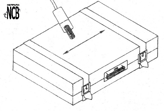
We then issue an alarm beep. Figure 1 illustrates how to use the detector by passing the sensor over a suitcase.
The sensor consists of a coil around a ferrite rod and to create the magnetic sensing field, a small magnet is attached to the assembly as shown in Figure 2.
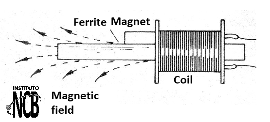
The more coils the coil has, the more sensitive the circuit will be. We recommend rolling 1 000 to 5 000 turns of fine wire or take advantage of a device reel that already has this coil, such as a residential cicada.
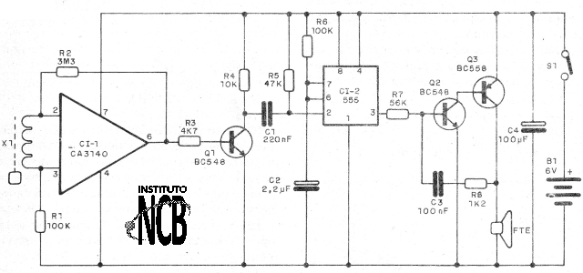
The circuit operates with a high gain operational amplifier at its input. The signal from this amplifier is applied to an amplifier transistor that triggers a 555 in the monostable version.
The alarm time is given by this circuit, set by R8, which can be changed over a wide range of values. The 555 output controls a small audio oscillator with two transistors whose frequency depends on R7 and capacitor C3.
These components can also be changed over a wide range of values.
Assembly
In figure 3 we have the diagram of the weapons detector.
For assembly, we can use a printed circuit board with the pattern shown in figure 4.
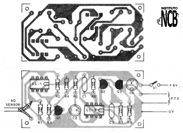
Observe the positions of the integrated circuits and transistors in the assembly. The resistors are 1/8 W with any tolerance and the electrolytic capacitors to 12 V or more.
The speaker can be 5 cm with 4 or 8 ohm and small batteries (AA) can be used for power. In figure 5 we have details of the coil using the spool of the primary winding of a small transformer from which the core has been withdrawn.
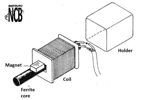
The magnet may be of the type found in objects to attach to refrigerators or of the type found in small engines. The final assembly of the apparatus in a plastic box is shown in figure 6.
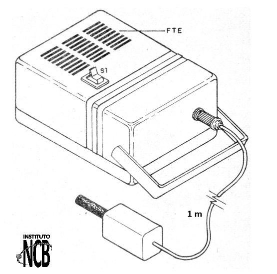
For connection of the sensor to the circuit, a shielded cable must be used, otherwise noise from the network of nearby devices can trip the circuit erratically. To test and use simply pass the sensor quickly near a metal object.
There should be the trip of the circuit with the emission of a sound through the speaker. To change the duration of the sound, change the value of resistor R5 and to change the tone, change R7.
CI-1 - CA3140 - integrated circuit
CI-2 - 555 - integrated circuit
Q1, Q2 - BC548 - general purpose NPN transistors
Q3 - BC558 - PNP general purpose transistor
X1 - Sensor - see text
S1 – On/Off switch
FTE - 4 or 8 ohm - small speaker
B1- 6 V - 4 small batteries
R1, R6 - 100 k ohm - resistors - brown, black, yellow
R2 - 1M2 ohm - resistor - brown, red, green
R3 - 4k7 ohm- resistor - yellow, violet, red
R4 - 10 k ohm - resistor - brown, black, orange
R5 - 47 k ohm - resistor - yellow, violet, orange
R7 - 56 k ohm - resistor - green, blue, orange
R8 - 1 k ohm - resistor - brown, black, red
C1 - 220nF - ceramic or polyester capacitor
C2 - 2.2 uF - electrolytic capacitor
C3 - 100 nF - ceramic or polyester capacitor
C4 100 uF - electrolytic capacitor
Several:
Printed circuit board, battery holder, mounting box, sensor material, wires, solder, etc.


