The powerful flashes of xenon lamps can be used for various purposes, the main being the signage and decoration. We describe in this article the assembly of a high-power luminous pushbutton that uses this type of lamp.
The circuit is given in two versions, one for operation on the 110 V network and the other for the 220 V network. What we have in the configuration used is a voltage doubler that carries an electrolytic capacitor with a voltage of the order of 600 V which is twice the peak of 220 V.
The energy stored in this capacitor is that it will produce the luminous pulse in the xenon lamp. To produce interval pulses, the stored high voltage is applied to a relaxation oscillator with a neon lamp.
The frequency of this oscillator and therefore the intensity and intervals between the flashes are set at P1.When the neon lamp fires, it also fires the SCR which then produces a high voltage pulse to ignite the xenon lamp.
As a result, the xenon bulb conducts and the high voltage capacitor discharges through it producing the strong luminous pulse. In figure 1 we have the possible forms of assembly for the device.
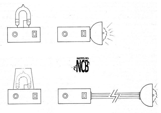
Assembly
Before we pass the assembly it is interesting to talk about the high voltage capacitor that will be used in the circuit. This capacitor can be availed from an out-of-use camera flash, or some other equipment, but first we must test it.
For this, we use the multimeter, as shown in figure 2.
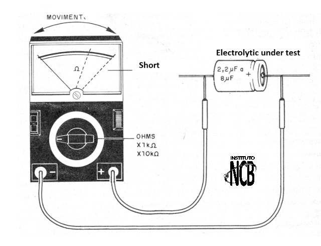
When playing with the probes the needle of the instrument moves to the regions of low resistance and then returns to high (an analog multimeter must be used). If it remains low, the capacitor should not be used.
In the same way, C1 and C2 should be tested, especially if they are taken advantage of by an appliance that is not in use.
In figure 3 we have then the circuit of the version for the network of 220 V.
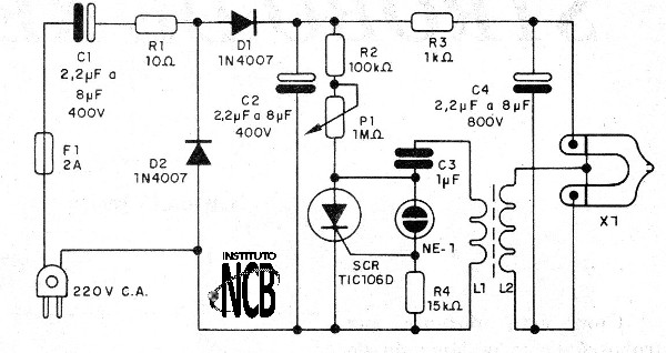
The printed circuit board for this assembly is shown in figure 4.
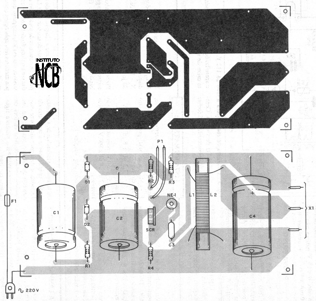
When installing, be careful of the polarity of the diodes and high voltage capacitors. The tripping transformer, formed by L1 and L2, is wound on a small ferrite rod.
L1 consists of 10 to 15 turns of enameled wire 26 to 30 AWG while L2 is formed by 200 to 500 turns of thin wire 32 or 30 AWG on L1. The resistors are 1/8 W with any tolerance except R1 which is ½ W or 1 W and R3 which is 2 to 5 W wire.
The 110 V network version is shown in figure 5.
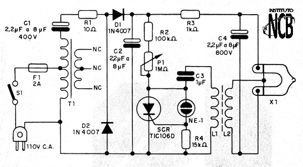
The printed circuit board for this version is shown in figure 6.
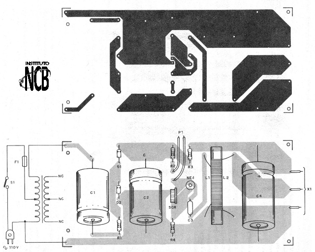
The only difference from the previous version is the presence of a self-transformer made with a small common power transformer with 5 to 12 V secondary and current between 500 mA and 800 mA, from which only the two-voltage primary indicated.
In both designs the SCR can be B or D suffix and the polyester capacitor of 100 V or more. For both designs the xenon lamp can be of any small type up to 100 mJ. To test and use, simply turn on the device and set the blink frequency to P1.
a) 220 V version
SCR - TIPC106 B or D - SCR
D1, D2 - 1N4007 - silicon diodes
NE-1 - common neon lamp
F1 - 2 A - fuse
X1 - xenon lamp - see text
L1, L2 - Pulse transformer - see text
P1 - 1 M ohm - potentiometer
C1, C2, C4 - 2.2 uF at 22 uF x 400 V - electrolytic capacitors
C3 - 1 uF - polyester capacitor
R1 - 10 ohm - resistor - brown, black, black
R2 - 100 k ohm - resistor - brown, black, yellow
R3 - 1 k ohm - 2 to 5 W - wire resistor
R4 - 15 k ohm - resistor - brown, green, orange
Several:
Printed circuit board, fuse holder, ferrite, power cable, wires, solder, etc.
b) 220 V version
The same as the previous version more:
T1 - Transformer with primary 110 V and 220 V and secondary of any voltage between 5 and 12 V with 500 mA at 800 mA


