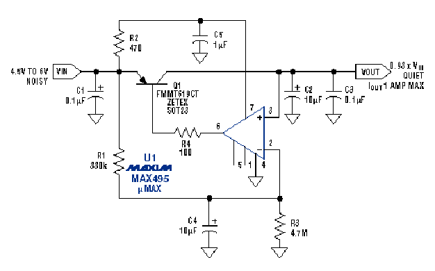
With this it is possible to provide a clean voltage of 5 V to power audio circuits in portable applications such as cell phones, MP3 players, notebooks, PDAs, etc. Most linear voltage regulators reject noise only up to or near 1000 Hz, which means that adding an additional filter is not something well seen in projects that are critical as to the available space.
The suggested configuration accepts noisy Vcc in the 4.5 V to 6 V range and produces Vcc at a 7% lower level. For example, the circuit will supply 4.65 V under 1 A with a nominal input voltage of 5 V and only 200 uA of quiescent current. The layout is very small, since it uses a SOT23 transistor, an operational amplifier in an SO-8 enclosure and some passive components. The largest component is the 10 uF capacitor. The resistors are 0.1 W for surface mounting.
In operation, the circuit operates as a buffered wideband voltage follower where the output level 7% lower than the input voltage is set. R1 and R3 form a voltage divider which provides these 7% attenuation and C4 helps to form a filter at 93% of the voltage.
The small input current bias current of the operational amplifier (25 nA tip) allows the use of high resistor values for R1 and R3 and further limits the maximum DC error by only 20 mV. The result is a low pass filter with 2 kHz cut and provides 20 dB attenuation at 20 kHz.
Like the input range of the amplifier in how it extends across the entire input rail (rail-to-rail) the input can sample the input voltage directly. The circuit feed is filtered by R2 and C5. These components provide lower output impedance and better source rejection for the operational amplifier at higher frequencies.
This filter has a 300 Hz rolloff that increases the PSSRR of the operational amplifier (still large by 110 dB).


