In a competition of bicycles or even races in the school, we can count on an "automatic match" that allows the verification of the speed of reflex of the competitors of automatic way. What we have is a circuit that keeps a red LED lit when we press S1, this for a time determined by the setting of the judge /
When this LED goes out, it simultaneously lights a green LED, thus enabling the output. In a "who knows best" competition, the system can be used to determine who first qualifies for a response, after the teacher asks the question and starts the device.
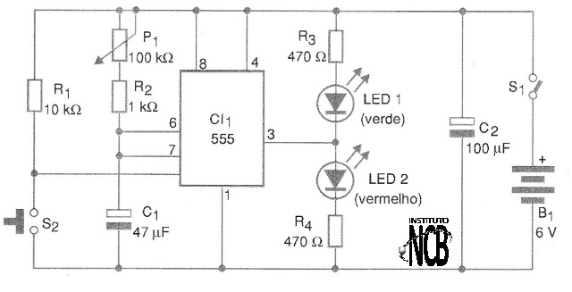
In figure 1 we have the complete diagram of the apparatus which is nothing more than a timer (monostable) based on the popular 555 integrated circuit.

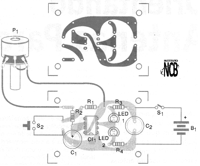
The arrangement of the components on a printed circuit board is shown in figure 2.

The circuit power comes from 4 small batteries and the brightness of the LEDs can be changed with the exchange of R3 and R4. These resistors can always have values above 220 ohm.
S2 is a "bell button" type pressure switch, which can be remote from the unit. The connection must be made through insulated wire.
In the P1 potentiometer the timing can be set from a few seconds up to about 1 minute. With the increase of C1 we can modify this range of times for up to more than 15 minutes with a capacitor of 1000 uF.
To test the device, first put P1 at any random position. Then simply turn on the power at S1. The green LED should light up. Then, by pressing S2 momentarily, the green LED turns off and the red LED lights up. Timing is started.
After some time, depending on the setting of P1, the red LED turns off and the green LED lights up. To use the device, each time you make a timing change the time in random mode in P1, in order to avoid that the competitors can have an idea of the drive time.
For this reason, it will be interesting that potentiometer P1 is hidden, so that competitors can’ see their position.
Semiconductors:
CI-1 - 555 - integrated circuit, timer
LED1, LED2 - Common red and green LEDs
Resistors: (1/8 W, 5%)
R1 - 10 k ohm - brown, black, orange
R2 - 1k ohm - brown, black, red
R3, R4 - 470 ohm - yellow, violet, brown
P1 - 100 k ohm at 470 k ohms - potentiometer
Capacitors:
C1 - 47 uF x 6 V - electrolytic
C2 - 100 uF x 6 V - electrolytic
Several:
S1 - Single switch
S2 - Pressure switch NA
B1 - 6 V - 4 small batteries
Printed circuit board, battery holder, mounting box, wires, solder, etc.


