The objective of this project is to set up a scale as easy and intuitive as possible, to highlight its functionalities linked to IoT.
Operation
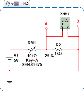
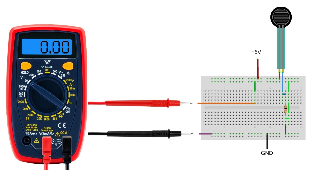
As we can see in Figure 1, we have the circuit and the assembly diagram.
When we put a weight on or put pressure on the RM1 resistive force sensor, the resistance between the terminals reaches a few kohm. When we have no weight or pressure on the RM1 resistive force sensor, the resistance between the terminals reaches Mohms (Megaohms).

The resistor R2 makes it possible to work with the sensor in order to read its values under no-load, under-loading and under-discharge conditions.
We use the multimeter to analyze the operation of the circuit, in other words, the electrical voltage present at the measurement point, which during the loading and unloading of the resistive force sensor. The reader can add LEDs to the system instead of the multimeter.
Assembly
The assembly is very simple, it was applied to a 440-pin protoboard. Below, we have a photo of the assembly and a video of its operation. The material used is easy to find and is found in the list below.
Link to video of its operation:
https://drive.google.com/open?id=1BnRXOS87-6TKhN0uOTwNIw3zpxrSTSDu
1 - 5V / 1A USB source (here, a simple cell phone charger with micro-USB connection fits well)
1 - resistive force sensor 0.5 "
1 - 1k / 0.25W resistor
1 - 440 point protoboard
Male-male and male-female jumpers
Conclusion
With this simple circuit, the resistive force sensor was tested, thus verifying its resistance variation inversely proportional to the load / force variation on it. Also, using this circuit topology used in this test, it is possible to verify (in a very similar way) the operation of any analog sensors that present as variable magnitude the resistance between their terminals (like an LDR, for example).


