PLLs are low-power circuits, but they can control high-power circuits that drive motors, solenoids, relays, and other loads. As with any other IC, PLLs are designated by part number.
From the part number, we can determine the device’s electrical specifications, which are important when designing with a PLL or even when finding a replacement part. The main specifications are as described below.
1. Power supply voltage range. This specifies the device’s functional voltage range.
2. Frequency range. This is a very important specification, as it indicates the highest signal frequency that can be recognized by a PLL, or generated by it when operating as an oscillator. Common general-purpose PLLs such as the 567 can operate at frequencies up to 500 kHz.
3. Sensitivity. This refers to the minimum signal amplitude that can be recognized by a PLL.
4. Output current. This specification indicates the amount of current the device can deliver or drain when driving a load.
In many modern applications, PLLs are included in more complex ICs. But there are also devices that offer the PLL as a single chip. Some common examples are the 4046, LM567, and other popular devices.
The following applications are indicative of how useful PLLS can be:
1. Remote control. A PLL can be used to recognize a tone sent by a transmitter (in the radio frequency or infrared band) and act on another device (a garage door opener motor or other electric or electronic appliance).
2. Intercoms. One type of intercom uses the AC power line to carry audio signals. The sounds picked up by a microphone are used to modulate a circuit, which produces an FM signal that is applied to the AC power line. A PLL in the receiver detects this signal and sends it to an amplifier.
3. Alarms and sensors. A tone is produced by a circuit and applied to a PLL via sensors. If any sensor is activated, the PLL detects the absence of the tone and triggers an alarm.
Test Procedures
The same test procedure recommended for ICs is valid here: measure the voltages at the pins and compare the readings with expected values.
Practical Circuits
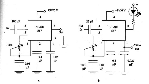
Two practical circuits using the LM567 are shown in Fig. 1. They are as described below.

Figure 1a - Tone detectorkthis circuit can be used to recognize a tone between 100 Hz and 200 kHz, depending on the adjustment of P1. When the tone is recognized, the output goes to the low logic level, driving the LED or relay.
Figure 1b - FM demodulator-this circuit can extract the low-frequency component of a high-frequency FM signal. Characteristics of the NE/LM567 are shown in Table 1.
Table 1 Characteristics of the NE/LM567
Frequency range: 0.1 to 500 kHz
Maximum operating voltage: 10 V
Input resistance (tip) 20: k ohm
Smallest detectable voltage: 20 mVrms
Operating voltage range: 4.5 to 9 V
Highest center frequency: 500 kHz
Output voltage (LOW)-IL = 100 mA: 0.6 V (tip)


