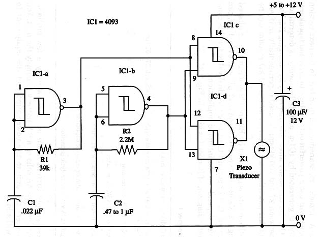
The circuit will produce an intermittent sound in a frequency of about 1 Hz. A piezoelectric transducer is used but, in the next version (Beeper ART162), we will use a powerful output stage to drive loudspeakers.
Audio tone is generated by ICl-a, and its frequency is determined by R1 and Cl. You can easily alter this frequency by changing R1. Values of R1 between 22 and 100 kg) can be used experimentally or, if you prefer, a 100 k ohm potentiometer in series with a 10 k ohm resistor can be used.
The repetition rate is governed by R2 and CZ and can also be altered by changing C2. Values between 0.15 and 0.47 µF, and even 1 µF, can be investigated. It is important to test for the ideal value for this component, which depends on the intended application.
A schematic diagram of Beeper is given in Fig. 1.

The power supply current drain is very low (only a few milliamperes), so you can use AA cells or a 9 V battery to supply the unit.
You can also connect the unit to the power supply of the equipment to which you will add it.
When using as a Shield you must power the 4093 from 5 V supplies and use pin 1 and 5 to control the oscillations.
IC1 - 4093 CMOS integrated circuit
X1 - Piezoelectric transducer or crystal earphone, Radio Shack 27 3-072 or equivalent
R1 - 39,000 ohm, 1/4 W, 5% resistor
R2 - 2,200,000 ohm, 1/4 W, 5% resistor
C1 - 0.022 µF metal film or ceramic capacitor
C2 - 0.47 to 1 µF metal film or ceramic capacitor
C3 - 100 µF, 12 WVDC electrolytic capacitor


