Note: this project is par of my book Science Fair and Technology Education Projects published in USA.
How it works
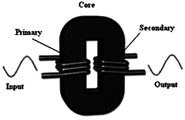
A transformer is formed by two coils wound with enameled wire. One of them is named primary and the other secondary. When we apply an AC voltage to the primary, the magnetic field generated by the current flow induces into the secondary a second voltage that appears in its extremes.
This voltage depends on the ratio of turns of the two coils. For instance, if the secondary has two times more turns than the primary, the voltage in the secondary will be two times the voltage applied to the primary coil. This means that transformers can be used to change voltages. Figure 1 shows the operation of the transformer.

The transformer needs current changes to operate. This can be explained because a stand field doesn’t induce voltages into a coil. That is because transformers only operate in AC circuits or circuits where the current changes are produced by a circuit or by a switch.
The experiment
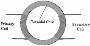
The experimental transformer uses a toroidal core (ring) and is built as shown in figure 2. Any iron or ferrite ring with a diameter in the range of 2 to 4 cm can be used. You can find many of these cores in old non-functioning PC power supply boards.

The coils are composed of about 50 to 100 turns of thin enameled wire (28 to 32) wound in the opposite sides of the ring as shown by the figure.
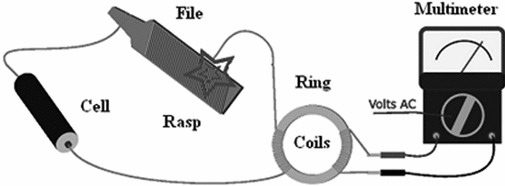
Thus, the magnetic field created by the primary produces force lines that run across the ring inducing a voltage in the second coil. The complete circuit for the experiment is in figure 3.

In order to show the operation of the transformer, scrape the wire on the file to produce a variable current, the condition necessary to create a variable magnetic field in the core.
This will cause the induction of a voltage in the secondary coil. This voltage will be indicated by the needle of the Multimeter. Of course, you can use a digital Multimeter, but better effects will be found by an analog Multimeter, because you will see the induction by the movement of the needle.
For a second step, you can show that if you keep the wire connected to the file, no voltage is induced. You can explain that the inductions occur only if the current changes. Don’t keep the wire in contact with the file for long time intervals. This will run down the battery.
Suggestions:
1. If you don’t have a Multimeter, you can replace it by a LED in series with a 470 ohm resistor (yellow, violet, brown). When scraping the wire against the file, the LED will light up.
2. The Galvanometer described in Project 2 is sensitive enough to detect the current induced in the secondary coil of the transformer.
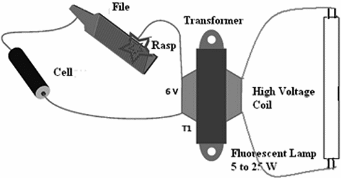
3. The same experiment can be performed using a common 117 V or 220/240 V to 3 to 12 V transformer with the secondary coil having currents in the range from 100 mA to 500 mA, as shown in figure 4. The fluorescent lamp can be replaced by a small neon lamp with the same final results.

Using this transformer, even having a single cell as power source, you can produce voltages high enough to cause strong shocks. Ask a friend to keep the wires of the transformer between his fingers. When you scrape the wire against the file, he will be surprised by a heavy but harmless shock.
Competition:
Using a LED or the Multimeter as reference, observe which of your pupils can build the transformer that generates the highest power.
1 AA or C cell
1 ring of ferrous material (iron, ferrite or other) - diameter of 2 to 4 cm
40 to 50 m of enameled wire (30 to 34 AWG)
1 Multimeter or Galvanometer
1 piece of sand paper or a blade


