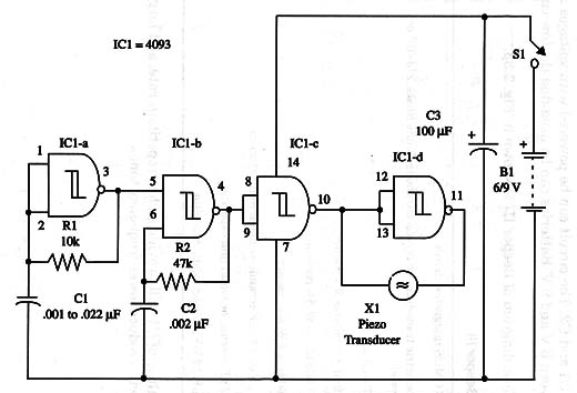
The frequency of the two oscillators can also be altered by changing capacitors Cl and C2. The circuit can be powered with voltages in the range between 6 V and 9 V. Batteries can be used due the low current drain.
A schematic diagram of Beeper III is shown in Fig. 1.

Large values of C1 will provide a slow repetition rate, and large values of C2 will produce lower-frequency tones.
Using as Shields: pins 1and 8 can be used as control. Power supply is limitted to 5 V.


