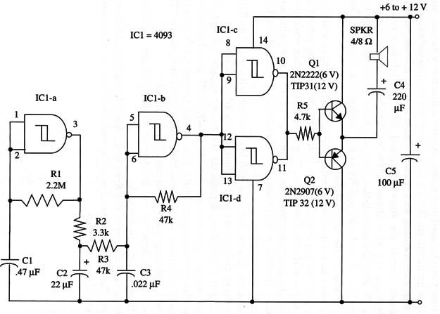
The circuit can be used as a siren, as part of alarms or games, and in many other applications. With a 12 V power supply, the output is up to few watts, representing an excellent audio level in a loudspeaker.
The basic circuit we show has fixed tone, modulation rate, and depth, but you can alter these characteristics by changing some components. To alter the modulation rate, you have to change R1 or Cl; to alter tone, you have to change R4 or C3. Modulation depth can be altered by changing R2 and also R3.
If you want to conduct some interesting experiments in sound generation, you can replace all of the indicated resistors by potentiometers in series with other resistors. The rule to make this replacement is simple: the potentiometer should have 2x or the same value as the substituted resistor, and the series resistor should have about 1/10 of the potentiometer value.
For instance, if you replace a 100 k ohm resistor with a 100 or 220 k ohm potentiometer, the series resistor should be a 10 or 22 k ohm unit.
The output transistors depend on the power supply voltage. For a 6 V power supply, you can use the 2N 2222/2N2907 pair, both general purpose silicon transistors. But if you intend to use a 9 V or a 12 V power supply, the transistors should be power units such as the TIP31/TIP32 pair, and they must be mounted on heatsinks.
Current drain depends on the power supply voltage. It typically ranges from 100 mA to 500 mA.
The circuit can be also controlled by a microcontroller such as the Arduino.
A schematic diagram of the Frequency-Modulated Siren is shown in Fig. 1.

The loudspeaker should be installed into an enclosure for better sound reproduction.
IC1 - 4093B CMOS integrated circuit
Q1 - 2N2222 or TIP31 (see text) NPN transistor
Q2 - 2N2907 or TIP32 (see text) PNP transistor
SPKR - 4/8 ohm, 4-inch loudspeaker
R1 - 2,200,000 ohm, 1/4 W, 5% resistor
R2 - 3,300 ohm, 1/4 W, 5% resistor
R3 -47,000 ohm, 1/4 W, 5% resistor
R4 - 47,000 ohm, 1/4 W, 5% resistor
R5 - 4,700 ohm, 1/4 W, 5% resistor
C1 -0.47 µF ceramic or metal film capacitor
C2 - 22 µF, 12 WVDC electrolytic capacitor
C3 - 0.022 µF ceramic or metal film capacitor
C4 - 220 µF, 16 WVDC electrolytic capacitor
C5 - 100 µF, 16 WVDC electrolytic capacitor


