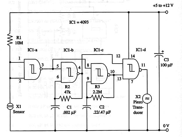
Circuit operation is easy to explain: when the sensor is touched, pin 2 (IC 1-a) goes low and the output goes high, triggering the two oscillators, formed by ICl-b and IC 1-c, to the “on” state.
Modulation and tone signals produced by these two oscillators are combined in the fourth gate (ICl-d) and applied to the output transducer. As in previous projects you can replace the piezoelectric transducer with transistorized output stages to drive loudspeakers.
The sensor is made with two small metal plates that should be touched at the same time to trigger the circuit. A schematic diagram of the device is shown in Fig. 1.

This device can be used as a touch alarm or in toys to produce sound effects when touched.
It also can be controlled by a microcontroller as the Arduino, PIC or MSP430 acting as a Shield. Power supply must be 5 V, according the microcontroller.
IC1 - 4093 CMOS integrated circuit
X1 - Metal plate sensor (see text)
X2 - Piezoelectric transducer or crystal earphone, Radio Shack 273-07 3 or equivalent
R1 - 10,000,000 ohm, 1/4 W, 5% resistor
R2 - 47,000 ohm, 1/4 W, 5% resistor
R3 - 2,200,000 ohm, 1/4 W, 5% resistor
C1 - 0.022 µF metal film or ceramic capacitor
C2 - 0.22 µF or 0.47 11F metal film or ceramic capacitor
C3 - 100 µF, 12 WVDC electrolytic capacitor


