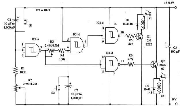
The circuit can be used as a sequential timer in several types of automatic systems. For instance, you can use this circuit as part of an “intelligent” alarm, first turning on a siren and then, after some minutes, a lamp. The second action of the circuit, turning on the lamp, suggests to the intruder the presence of another human in the vicinity.
You can use it to replace a more complex resource such as the Arduino for simple purposes.
The circuit can be powered from 6 or 12 V supplies. In alarm systems, you should use heavy-duty batteries or ac power supplies, because, when closed, the two relays drain an amount of current exceeds the capacity of small AA cells and other small batteries.
With the dual time delays, you can obtain a total time delay of up to an hour and half.
A schematic diagram of the Dual Turn-On Timer is shown in Fig.1.

Proper positioning of the polarized components (the two diodes and the electrolytic capacitors) must be observed. Using mini DPDT relays, it’s easy to build a compact unit, as these components can be mounted directly on the solderless board or universal printed circuit board.
IC1 - 4093 CMOS integrated circuit
Q1 - 2N 2222 NPN general purpose silicon transistor
Q2 - 2N2907 PNP general purpose silicon transistor
D1, D2 - 1N4148 general purpose silicon diodes
K1, K2 - 6 or 12 V relay, 100 mA coil (Radio Shack 275-249, 12 Vdc, 43 mA,
280 ohm, is a suitable unit)
S1, S2 - SPST momentary switch
R1, R4 - 100,000 ohm, 1/4 W, 5% resistors
R2, R3 - 2,200,000 ohm or 4,700,000 ohm potentiometers
R5, R6 - 4,700 ohm, 1/4 W, 5% resistors
Cl, C2 - 10 µF to 1,000 µF, 12 WVDC electrolytic capacitors (see text)
C3 - 100 µF, 16 WVDC electrolytic capacitor


