The timer is powered from four AA cells or a 9 V battery. Current drain is very low (only few milliamperes), which extends the power supply life to many weeks.
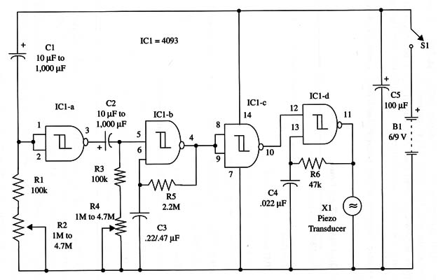
A schematic diagram of the Dual Pulsed-Tone Timer is shown in Fig. 1.

The proper positions of the polarized components (electrolytic capacitors and battery) must be observed. To obtain a compact version, you can use a small printed circuit board.
Time delays are determined by capacitors C1 and C2. With 1,000 µF capacitors, the maximum time delay for each is 45 minutes. Total time delay is more than 90 minutes.
The tone is determined by R6 and C4, and the pulse rate is given by R5 and C3. These components can be changed to alter the final tone.
In operation, adjust the time delays via R2 and R4, and close power switch (81). After the time delay adjusted by R2, a tone will be produced during a time interval given by the R4 adjustment.
IC1 - 4093 CMOS integrated circuit
X1 - Piezoelectric transducer or crystal earphone, Radio Shack 279-073 or equivalent
S1 - SPST toggle or slide switch
B1 - 6 or 9 V (four AA cells or battery)
R1, R3 - 100,000 ohm, 1/4 W, 5% resistors
R2, R4 - 1,000,000 ohm to 4,700,000 ohm potentiometers or trimmer potentiometers
R5 - 2,200,000 ohm, 1/4 W, 5% resistor
R6 - 47,000 ohm2, 1/4 W, 5% resistor
C1, C2 - 10 µF to 1,000 µF, 12 WVDC electrolytic capacitors
C3 - 0.22uF or 0.47 µF ceramic or metal film capacitor
C4 - 0.022 µF ceramic or metal film capacitor
C5 - 100 µF, 12 WVDC electrolytic capacitor


